Composite insulating building panel and system and method for attaching building panels

a technology of composite panels and building panels, which is applied in the field of composite panels, can solve the problems of degrading the thermal performance of the insulation, reducing and not providing a continuous insulation envelope, so as to increase the esthetics of the panel, reduce the amount of blistering, and increase the strength and durability of the composite panel

Active Publication Date: 2011-08-18
PACIFIC INSULATED PANEL
View PDF40 Cites 39 Cited by
  • Summary
  • Abstract
  • Description
  • Claims
  • Application Information

AI Technical Summary

Benefits of technology

[0006]One aspect of this invention is to provide an improved composite insulation panel system incorporating an integrated seal tab that allows adjoining panels to be jointed during installation with a pre-installed adhesive. This enables the installed panels to have a continuous air and vapor resistant barrier in addition to increased strength and durability of the composite panel through integrated fiber placement. Another aspect of this invention is to provide an improved method of manufacturing a composite panel using textured mold inserts, which allow air trapped between the heated platens and the composite facing to escape. This also imparts an embossed textu...

Problems solved by technology

Laminated fiberglass insulation used in pre-manufactured buildings has limitations as it does not provide a continuous insulation envelope.
When this method is used, the fiberglass laminate is compressed over the framing by the roof and siding panels, thereby degrading the thermal performance of the insulation.
While this system addresses the issue of compressed fiberglass it still carries most of the drawbacks of a loose fill insulation system.
Loose fill fiberglass systems are virtually unable to block air infiltration and water vapor, which can drastically reduce the thermal performance of the insulation system.
Additionally...

Method used


Image

  • Composite insulating building panel and system and method for attaching building panels
  • Composite insulating building panel and system and method for attaching building panels
  • Composite insulating building panel and system and method for attaching building panels

Examples


Embodiment Construction

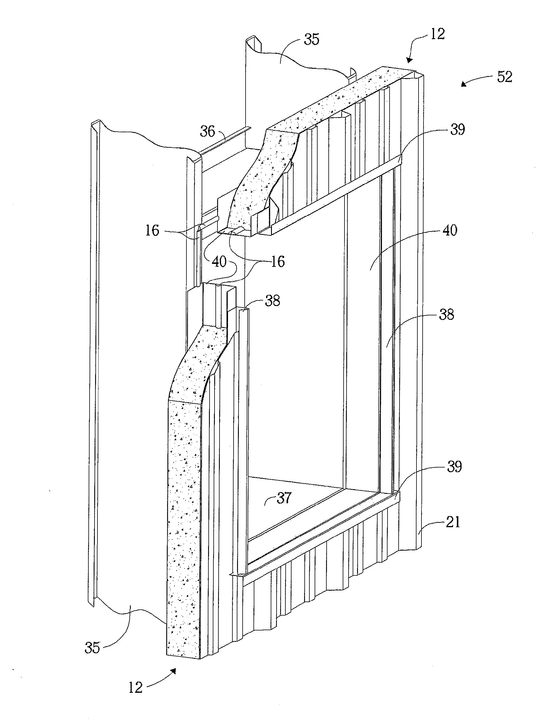
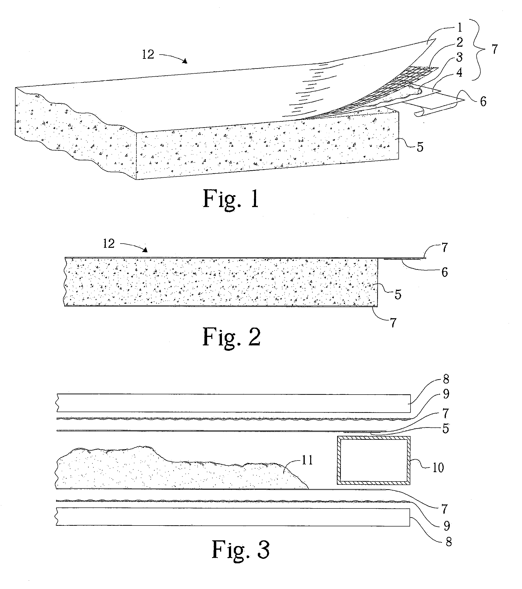
[0017]Turning now to the drawings, wherein like reference characters designate identical or corresponding parts, and more particularly to FIG. 1 thereof, a composite insulation panel 12 embodying aspects of the invention includes a facing 7 disposed on one side, or, alternatively, both sides, of a foam core 5. Top facing 7 of the composite panel 12 is shown in FIG. 1 pulled back to expose its components. Facing 7 may comprise, but is not limited to, a vapor impervious skin 1, preferably between 2.5 and 400 micron, beyond which a reinforcing layer may be redundant. By way of a specific example the skin 1 is comprised of metalized polypropylene. Other suitable materials include a wide range of polymeric materials; for example, polystyrene, polyethylene, polypropylene, polyurethane, and polyvinylchloride. In some cases, for costs savings, a facing material can become increasingly thin to a point at which it is no longer a vapor impervious skin. Thinner skins can be more cost effective,...


PUM

PropertyMeasurementUnit
Thicknessaaaaaaaaaa
Dimensionaaaaaaaaaa
Thermal propertiesaaaaaaaaaa

Abstract

An insulation panel includes a foam core with a reinforced and vapor-impervious facing disposed on one or both sides of the core. A portion of the facing extends beyond the core and has an adhesive so that the overhanging portion can be secured to an abutting panel to cover a seam between the abutting panels. A fixture for forming the panel includes two heated platens, preferably provided with a textured surface, held apart by a spacer and between which the facing is mechanically suspended. An installation of the insulation panel includes panel-securing elements attached to frame elements of the building and including first and second flanges spaced apart by the thickness of the panel. A portion of the insulation panel is disposed between the first and second flanges, the first flange is secured to the frame element, and a cover panel disposed over the insulation panel is secured to the second flange.

Description

CROSS-REFERENCE TO RELATED APPLICATIONS[0001]This application claims the benefit under 35 U.S.C. 119(e) of U.S. Provisional Application No. 61 / 294,564, filed Jan. 13, 2010, the disclosure of which is hereby incorporated by reference in its entirety.FIELD OF THE INVENTION[0002]This invention relates in general to composite panels for industrial insulation, and more particularly to composite panels including two composite facings, at least one of which overhangs a foamed-in-place plastic core, with an adhesive placed on the overhang, as well as systems, devices, and methods for manufacturing and installing such panels.BACKGROUND OF INVENTION[0003]With increasing emphasis being placed on thermal performance of industrial insulation and an increasing number of organizations and regulatory bodies such as ASHRAE and the DOE, pressure is being placed on an industry that has lacked an economical solution that encompasses both a continuous insulated envelope and an insulation system that add...

Claims


Application Information

Patent Timeline
IPC IPC(8): E04B2/46E04B1/62E04C2/20
CPCB32B5/14B32B5/18B32B5/26B32B15/08B32B15/14E04C2/243E04B1/80E04H5/10E04B1/74E04C2/205E04B1/765B32B5/024B32B7/12B32B15/18B32B15/20B32B27/12B32B27/302B32B27/304B32B27/32B32B27/40B32B29/007B32B29/02B32B2255/06B32B2255/10B32B2255/205B32B2255/26B32B2262/101B32B2262/106B32B2266/0228B32B2266/0235B32B2266/0278B32B2307/304B32B2307/3065B32B2307/50B32B2307/581B32B2307/7246B32B2307/732B32B2607/00E04D3/358Y10T428/24355Y10T428/24785Y10T442/3195Y10T442/3325Y10T442/3333Y10T442/335B32B5/245B32B2250/40B32B2262/10B32B2419/00
Inventor BAHNMILLER, JEFFREY A.
Owner PACIFIC INSULATED PANEL
Why Eureka
Try Eureka