Detector arrangement for a tomographic imaging apparatus, particularly for a positron emission tomograph

a tomographic imaging and detector arrangement technology, applied in the direction of measurement devices, instruments, material analysis through optical means, etc., can solve the problems of unsatisfactory detection performance of these conventional detector arrangements and the corresponding detector rings, and achieve the effect of shortening the decay time, improving the detection performance, and improving the detection performan

Inactive Publication Date: 2011-08-18
BERGEN TEKNOLOGIOVERFORING
View PDF10 Cites 23 Cited by
  • Summary
  • Abstract
  • Description
  • Claims
  • Application Information

AI Technical Summary

Benefits of technology

[0021]Alternatively, it is possible to use organic scintillators having a shorter decay time facilitating a run time calculation thereby improving the detection performance.
[0022]Therefore, at least one of the scintillators preferably may comprise a shorter decay time than the other scintillators thereby facilitating a precise run-time calculation. In a three-layer arrangement, two of the scintillators may consist of inorganic scintillator crystals while the other scintillator is an organic scintillator having a shorter decay time thereby facilitating a precise run-time calculation. For example, the decay time of the inorganic scintillators is typically longer than 20 ns while the shorter decay time of the organic scintillators is typically less than 5 ns.

Problems solved by technology

Hence, the detection performance of these conventional detector arrangements and the corresponding detector rings is unsatisfactory.

Method used


Image

  • Detector arrangement for a tomographic imaging apparatus, particularly for a positron emission tomograph
  • Detector arrangement for a tomographic imaging apparatus, particularly for a positron emission tomograph
  • Detector arrangement for a tomographic imaging apparatus, particularly for a positron emission tomograph

Examples


Embodiment Construction

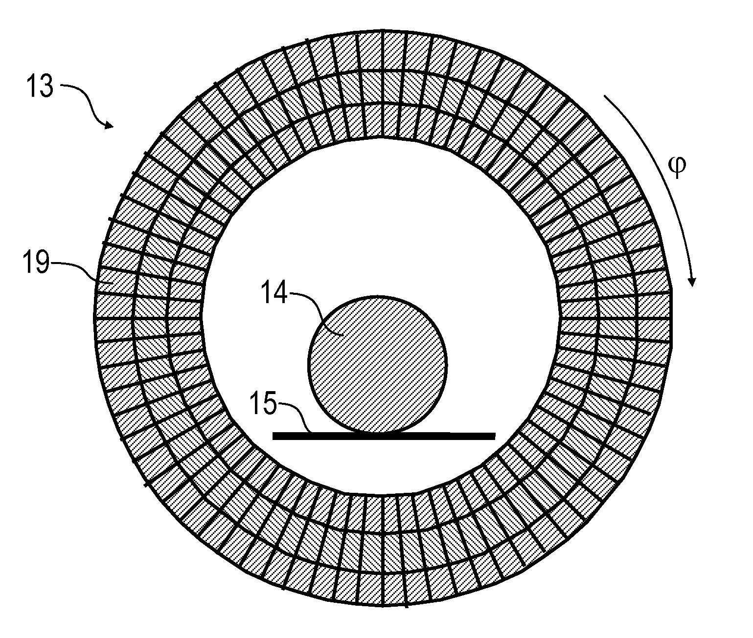
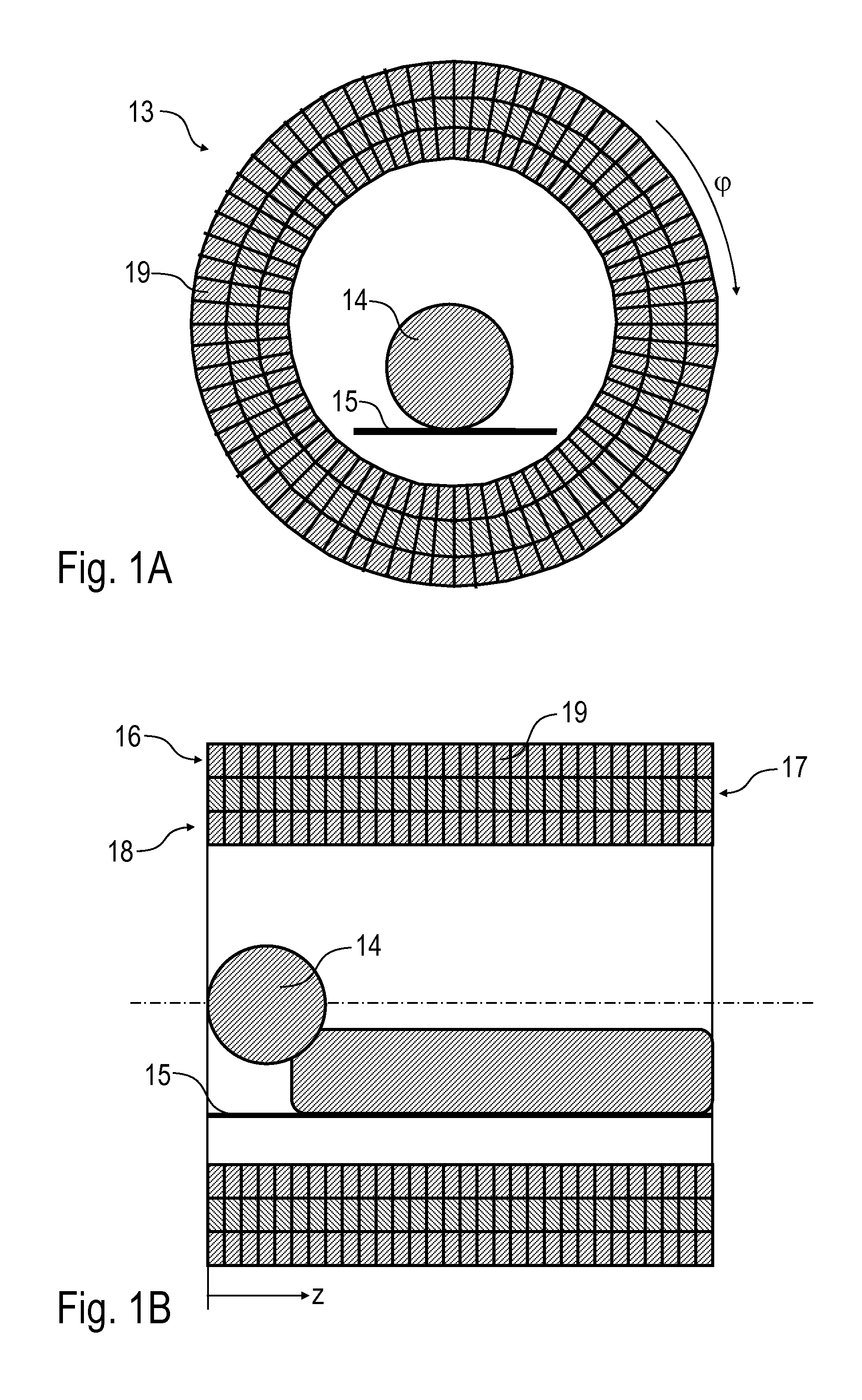
[0051]FIGS. 1A-1D illustrate a detector ring 13 surrounding a patient 14 on a patient bed 15, wherein the detector ring 13 comprises three layers 16, 17, 18 of scintillator crystals 19 and associated photodetectors, wherein the photodetectors are pixelated avalanche photodetectors operated in the Geiger-mode.

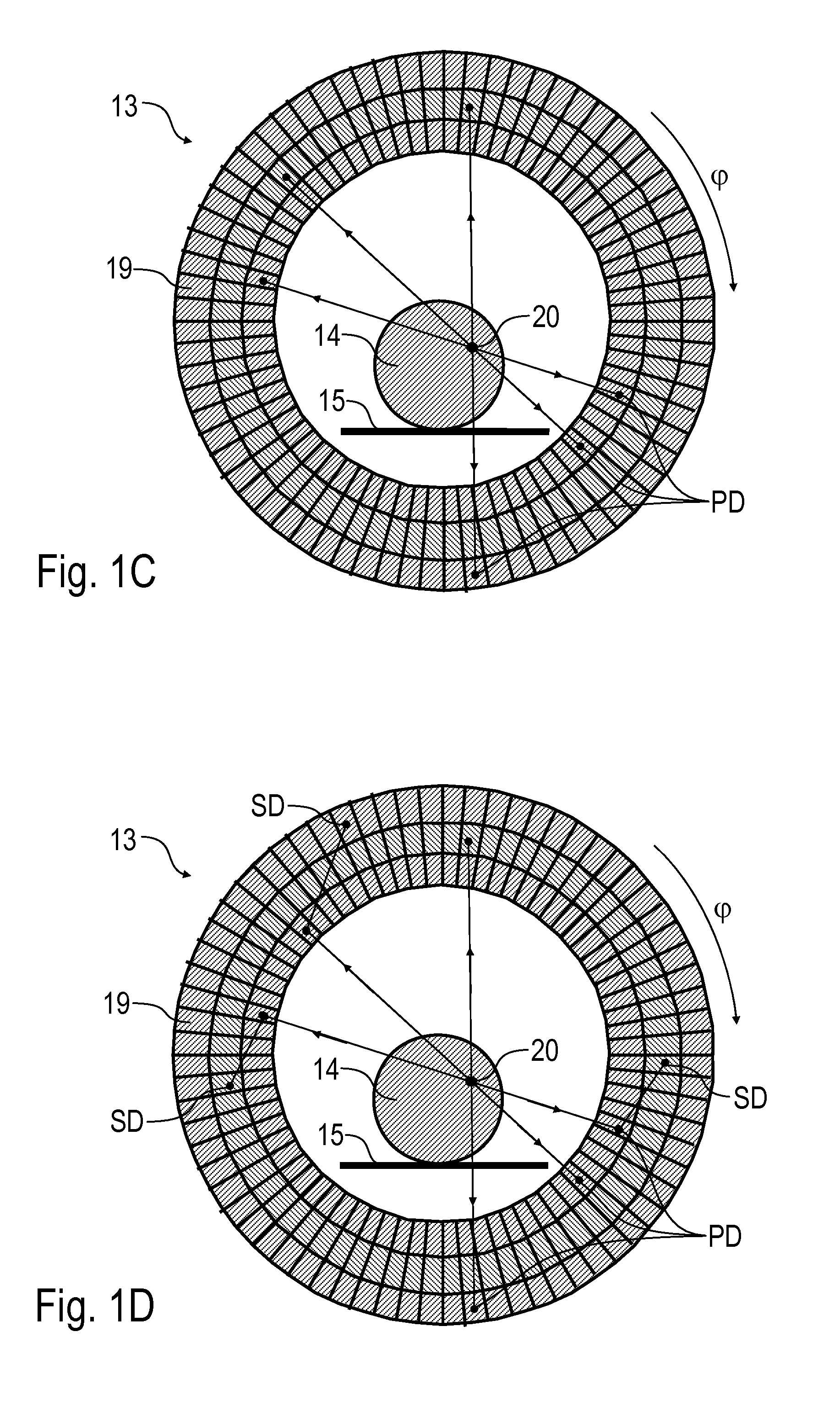
[0052]FIG. 1C illustrates a positron-electron annihilation 20 within the patient 14 resulting in the generation of a pair of Gamma photons which are irradiated in opposing directions. Further, the drawing shows primary photon detections PD in the individual layers 16-18 of the detector rings 13, i.e. photon detections with an energy corresponding to the annihilation energy of 511 keV.

[0053]Further, FIG. 1D illustrates both primary photon detections PD and secondary photon detections SD caused by Compton-scattering in the inner layers 17 or 18 of the detector ring 13. It has to be noted that the Gamma photons generated by the positron-electron annihilation 20 in the patient 14 ar...


PUM


Abstract

The invention relates to a detector arrangement (21) for a tomographic imaging apparatus, particularly for a positron emission tomograph. The detector arrangement (21) according to the invention includes at least two sandwiched pairs of a scintillator (22-24) and an associated photodetector (25-27), wherein the pairs are sandwiched along a direction of detection.

Description

FIELD OF THE INVENTION[0001]The invention relates to a detector arrangement for a tomographic imaging apparatus, particularly for a positron emission tomograph (PET).[0002]Further, the invention relates to a detector ring comprising a plurality of the detector arrangements according to the invention and a tomographic imaging apparatus comprising such a detector ring.[0003]Moreover, the invention relates to an operating method for a tomographic imaging apparatus, particularly for a positron emission tomograph.BACKGROUND OF THE INVENTION[0004]Positron emission tomography (PET) is a nuclear medicine imaging technique producing three-dimensional images of functional processes in the body. The conventional PETs comprise a detector ring for detection of Gamma rays emitted indirectly by a positron-emitting radio nuclide (tracer), which is introduced into the body on a biologically active molecule. The conventional detector rings currently used in PETs comprise a plurality of detector arran...

Claims


Application Information

Patent Timeline
Patent Type & Authority Applications(United States)
IPC IPC(8): G01T1/20
CPCG01T1/2985G01T1/202
Inventor EIGEN, GERALD
Owner BERGEN TEKNOLOGIOVERFORING
Why Eureka
Try Eureka