
Device and method for standby power supply on board an aircraft

a technology for aircraft and power supply, applied in the direction of energy-efficient board measures, electric generator control, greenhouse gas reduction, etc., can solve the problems of inability to ensure the manoeuvrability of aircraft, the power generation of electricity is very rapidly halted, and the longer the time, so as to improve the sturdiness

Inactive Publication Date: 2011-08-18
AIRBUS OPERATIONS (SAS)
View PDF3 Cites 14 Cited by
  • Summary
  • Abstract
  • Description
  • Claims
  • Application Information

AI Technical Summary

Benefits of technology

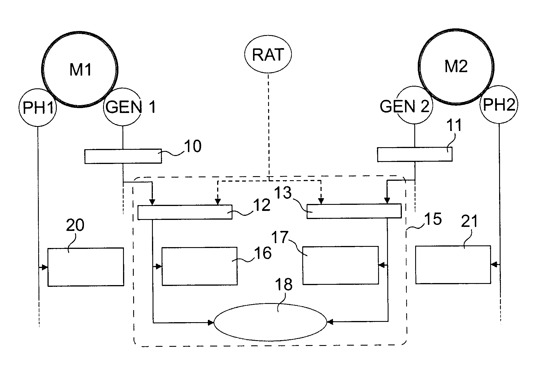
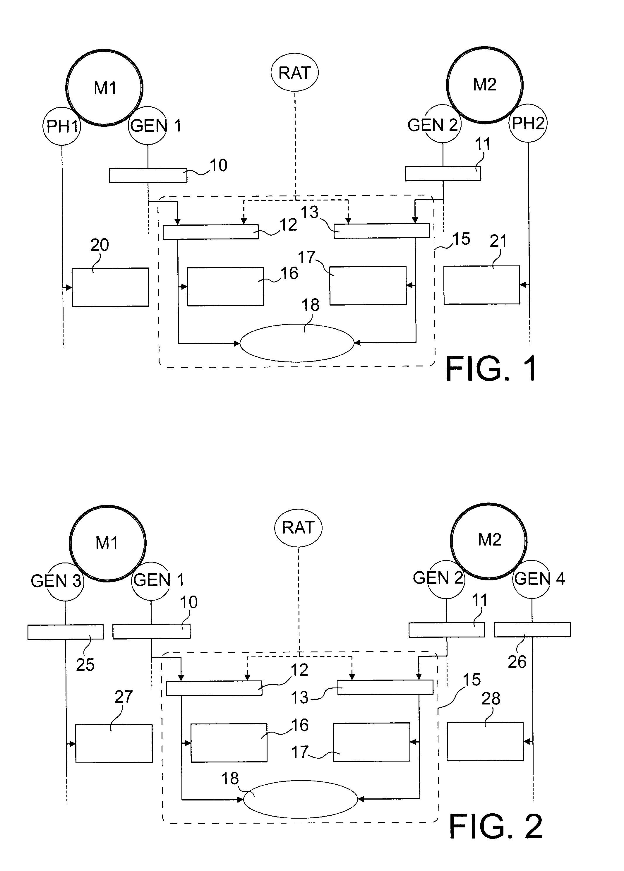
[0042]It can ensure coverage of the transitory periods: the providing of a storage device of flywheel type can ensure availability of the electrical power circuit during transitory periods of inactivity of the electric power source e.g. of the ram air turbine. This function is particularly useful during the moments following after total engine loss and on aircraft landing. Said advantage applies to any airplane having an emergency electric power source.
[0043]It can be directly coupled to the airplane's three-phase AC network: the flywheel associated with a three-phase electric machine allows direct coupling to the airplane's three-phase circuit, without the use of static converters. This is of particular interest insofar as significant experience is acquired with respect to alternating current in aeronautics. The absence of a static converter provides for improved sturdiness with the use of simple systems only. Said advantage applies to an airplane having at least part of the emergency electric power circuit in AC.

Problems solved by technology

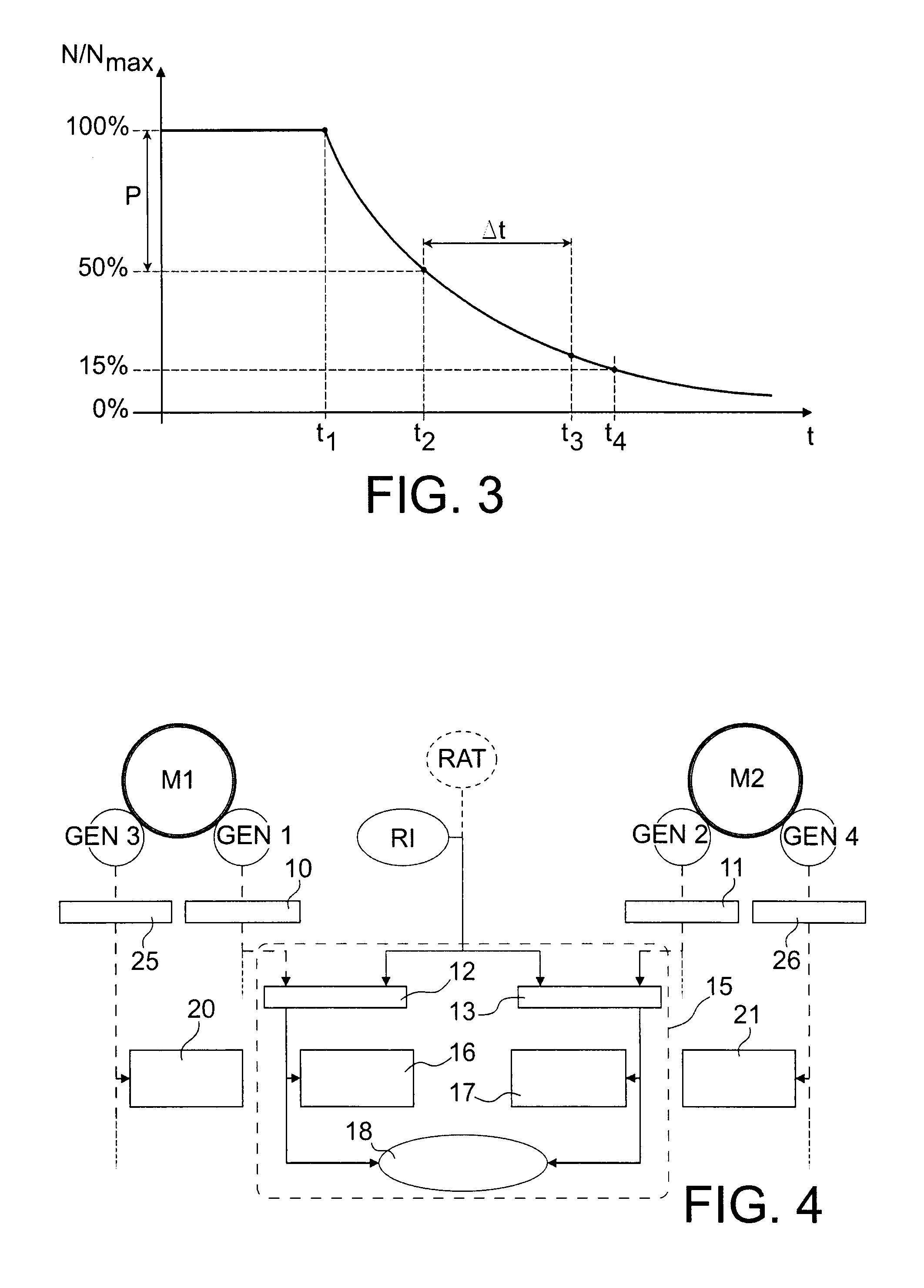
In the event of total loss of power from the engines, a technical problem arises related to the transitory period occurring between this total loss and the effective entry into service of the emergency power supply.
On the other hand, the generation of electricity is very rapidly halted after engine loss owing to electric frequency constraints which prevent use of the electricity generators at low rotating speeds.
On an > airplane, the absence of hydraulic energy therefore means that coverage of the transitory period Δt can no longer be ensured just after engine loss, and hence airplane manoeuvrability cannot be ensured.
A ram air turbine RAT is ineffective at low aircraft speed, after landing.
Yet braking of the airplane's wheels requires substantial power and energy.

Method used


Image

  • Device and method for standby power supply on board an aircraft
  • Device and method for standby power supply on board an aircraft
  • Device and method for standby power supply on board an aircraft

Examples


Embodiment Construction

a > airplane having a hydraulic circuit, emergency braking is achieved by means of hydraulic accumulators which can feed the brakes by releasing their fluid at a given pressure. On the other hand, in an > airplane, the energy required for braking must therefore be provided by an electricity source other than the ram air turbine.

[0028]The object of the invention is to propose a device and method to supply emergency power allowing coverage of these transitory periods.

DESCRIPTION OF THE INVENTION

[0029]The invention concerns a device for emergency electricity supply on board an aircraft, able to supply the > part of the aircraft's electrical power circuit, characterized in that it comprises a first synchronous machine with separate excitation associated with an inertia flywheel, and an auxiliary device for setting the flywheel in rotation and maintaining its rotation.

[0030]In one advantageous embodiment, the device of the invention also comprises a second synchronous machine with separa...


PUM


Abstract

A device and a method for emergency electricity supply on board an aircraft, able to supply a part of the aircraft's electrical power circuit. The device includes a synchronous machine with separate excitation, associated with a flywheel, and an auxiliary device to set the flywheel in rotation and to maintain rotation of the flywheel.

Description

TECHNICAL AREA[0001]The invention concerns a device and a method for emergency electricity supply on board an aircraft, for example an <<all-electric>> aircraft.STATE OF THE PRIOR ART[0002]In the remainder of the description consideration is given by way of example to an aircraft of airplane type.[0003]One source of emergency electrical power frequently used on a <<more electric aircraft>> is a Ram Air Turbine—RAT, which drives an electric generator via a step-up gear.[0004]In emergency situations on board an airplane, said ram air turbine can be used to generate sufficient electric power to enable this airplane to fly for a sufficient length of time and to land.[0005]A ram air turbine comprises a propeller which is actuated by air at high speed circulating against the airplane. The propeller, which therefore rotates, drives an electric generator which provides the necessary emergency power to supply the <<essential>> part of the electrical power ...

Claims


Application Information

Patent Timeline
IPC IPC(8): B60L1/00H02K7/18
CPCB64D41/00B64D41/007B64D2041/002B64D2221/00Y02T50/54F05B2220/50Y02E10/725Y02T50/44Y02T50/545F03D9/002F03D9/12Y02E60/16F03D9/25Y02E10/728F03D9/32Y02E10/72Y02T50/50Y02T50/40Y02E70/30
Inventor LANGLOIS, OLIVIERFOCH, ETIENNE
Owner AIRBUS OPERATIONS (SAS)
Learn More