Wireless power feeder, wireless power receiver, and wireless power transmission system

a technology of wireless power transmission system and wireless power feeder, which is applied in the direction of transmission, transformer, inductance, etc., can solve the problems of degrading resonance characteristics, increasing and not being able to feed big electric power, so as to achieve the effect of suppressing the size of the coil and increasing the number of windings

Active Publication Date: 2011-08-18
TDK CORPARATION
View PDF53 Cites 30 Cited by
  • Summary
  • Abstract
  • Description
  • Claims
  • Application Information

AI Technical Summary

Benefits of technology

[0030]According to the present invention, it is possible to easily increase the number of windings of a coil used in wireless power feeding of a magnetic field resonance type while suppressing the size of the coil.

Problems solved by technology

The type (B) utilizing radio wave is available in a long range; however, it cannot feed big electric power.
However, this increases the size of the coil.
Further, when the coil is wound closely, the stray capacitance between coil conductors is increased, which poses a problem that resonance characteristics are degraded.

Method used


Image

  • Wireless power feeder, wireless power receiver, and wireless power transmission system
  • Wireless power feeder, wireless power receiver, and wireless power transmission system
  • Wireless power feeder, wireless power receiver, and wireless power transmission system

Examples


first embodiment

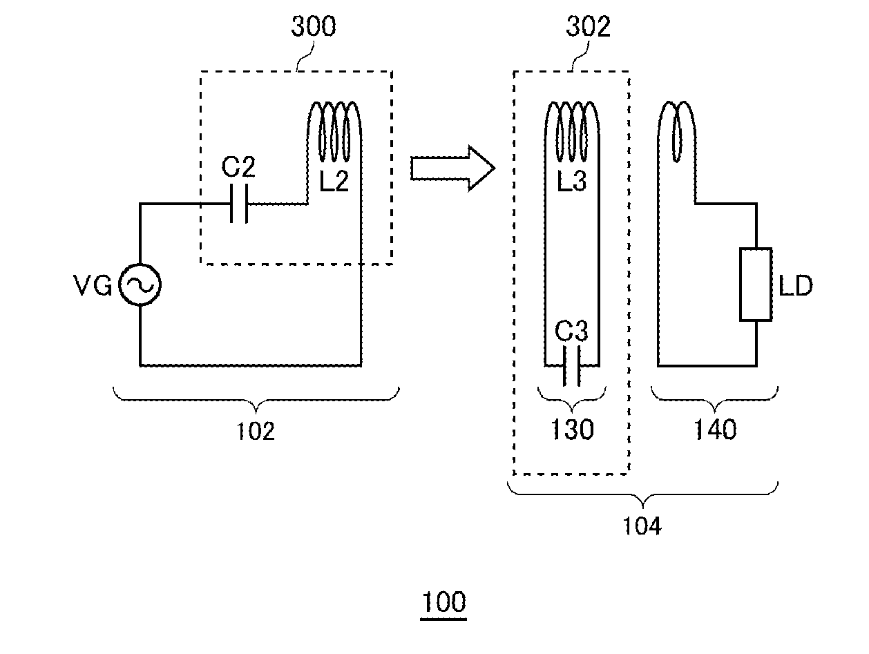
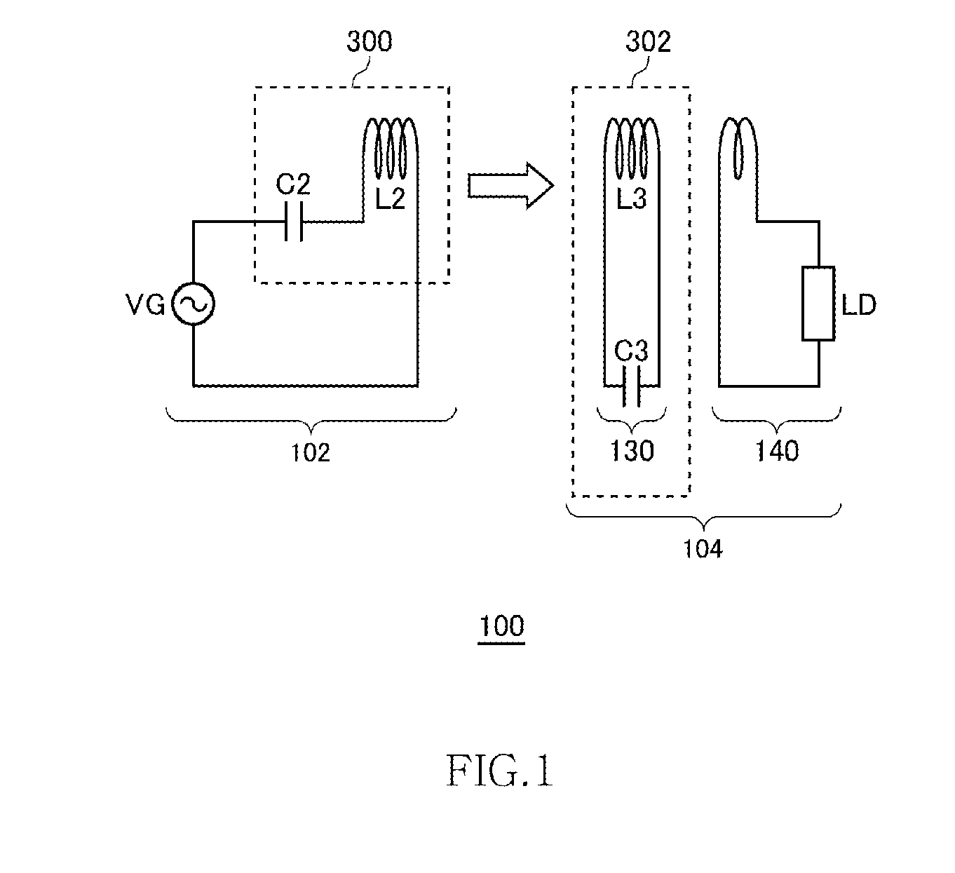
[0048]FIG. 1 is a view illustrating operation principle of a wireless power transmission system 100 according to the first embodiment. The wireless power transmission system 100 in the first embodiment includes a wireless power feeder 102 and a wireless power receiver 104. The wireless power feeder 102 includes a power feeding LC resonance circuit 300. The wireless power receiver 104 includes a receiving coil circuit 130 and a loading circuit 140. A power receiving LC resonance circuit 302 is formed by the receiving coil circuit 130.

[0049]The power feeding LC resonance circuit 300 includes a capacitor C2 and a feeding coil L2. The power receiving LC resonance circuit 302 includes a capacitor C3 and a receiving coil L3. The values of the capacitor C2, feeding coil L2, capacitor C3, and receiving coil L3 are set such that the resonance frequencies of the feeding LC resonance circuit 300 and receiving LC resonance circuit 302 coincide with each other in a state where the feeding coil L...

second embodiment

[0083]FIG. 14 is a view illustrating operation principle of the wireless power transmission system 100 according to a second embodiment. As in the case of the first embodiment, the wireless power transmission system 100 according to the second embodiment includes the wireless power feeder 102 and wireless power receiver 104. However, although the wireless power receiver 104 includes the power receiving LC resonance circuit 302, the wireless power feeder 102 does not include the power feeding LC resonance circuit 300. That is, the feeding coil L2 does not constitute a part of the LC resonance circuit. More specifically, the feeding coil L2 does not form any resonance circuit with other circuit elements included in the wireless power feeder 102. No capacitor is connected in series or in parallel to the feeding coil L2. Thus, the feeding coil L2 does not resonate in a frequency at which power transmission is performed.

[0084]The power feeding source VG supplies AC current of the resonan...


PUM

PropertyMeasurementUnit
frequencyaaaaaaaaaa
distanceaaaaaaaaaa
resonance frequencyaaaaaaaaaa

Abstract

Power is fed from a feeding coil to a receiving coil using magnetic resonance. The feeding coil is wound in a first layer substrate 144 of a multilayer substrate 116 with a space provided between the coil conductor thereof and further wound in a second later substrate 146 with a space provided between the coil conductor thereof. The feeding coil is wound such that a coil conductor 106a in the first layer and a coil conductive wire 106b in the second layer do not overlap each other as viewed in the axial direction (z-axis direction).

Description

BACKGROUND OF THE INVENTION[0001]1. Field of the Invention[0002]The present invention relates to structures of coils used in wireless AC power feeding / receiving.[0003]2. Description of Related Art[0004]A wireless power feeding technique of feeding power without a power cord is now attracting attention. The current wireless power feeding technique is roughly divided into three: (A) type utilizing electromagnetic induction (for short range); (B) type utilizing radio wave (for long range); and (C) type utilizing resonance phenomenon of magnetic field (for intermediate range).[0005]The type (A) utilizing electromagnetic induction has generally been employed in familiar home appliances such as an electric shaver; however, it can be effective only in a short range of several centimeters. The type (B) utilizing radio wave is available in a long range; however, it cannot feed big electric power. The type (C) utilizing resonance phenomenon is a comparatively new technique and is of particula...

Claims


Application Information

Patent Timeline
Patent Type & Authority Applications(United States)
IPC IPC(8): H01F38/14
CPCH01F38/14H04B5/0093H04B5/0037H02J5/005H02J50/502H02J50/12
Inventor URANO, TAKASHI
Owner TDK CORPARATION
Why Eureka
Try Eureka