Solid-state light source device

a light source device and solid-state technology, applied in the direction of point-like light sources, lighting and heating devices, instruments, etc., can solve the problems of not necessarily providing a light source suitable for projection-type display devices, reducing the brightness of the lamp itself, and difficulty in disposing waste materials thereof, so as to reduce the consumption of electric power

Active Publication Date: 2011-08-18
MAXELL HLDG LTD
View PDF13 Cites 100 Cited by
  • Summary
  • Abstract
  • Description
  • Claims
  • Application Information

AI Technical Summary

Benefits of technology

[0019]According to the present invention mentioned above, it is possible to achieve the solid-state light source device for enabling to obtain white color light emitting from an approximately point-like light source, while applying a solid-state light source as the light source. From that, the solid-state light source device can be adopted, in particular, as the light source in the lighting optic system of the projection-type display apparatus, easily, in the place of the conventional super or ultra high-pressure mercury lamp, and thereby obtaining an effect that the optic system portions of the projection-type display apparatus can show the optical performances thereof, fully, comparing to the conventional art; i.e., it is possible to provide a projection-type display apparatus, being improved much more than the conventional art, against generation of deterioration of white-balance and / or color shading on a projection surface, and also reduce the consumption of electric power of the apparatus, greatly, comparing to the conventional one.

Problems solved by technology

Also, the lamp itself brings about lowering of brightness due to abrasion of electrodes and / or cloudiness of a light emitting tube, in a relatively short time period.
Further, it has a problem of difficulty in disposal of waste matter thereof, etc., because it contains mercury therein.
And, as was mentioned above, though various kinds of the light sources are proposed for the projection-type display apparatus, applying the light emitting diodes and / or the laser diodes therein, in the place of such super high-pressure mercury lamp, in the Patent Document(s) mentioned above; however, in particular, the light source for the projection-type display apparatus has the following problems.
On the contrary to this, the light source devices (i.e., the solid-state light sources), which are proposed by the conventional arts including the Patent Documents mentioned above, do not necessarily provided a light source being suitable for the projection-type display apparatus.
Thus, the light obtainable from the light source devices according to the conventional arts mentioned above are collection or assemblage of lights from a large number of solid-state light sources, which are disposed integrally within a relatively large area, and for that reason, it does not build up a point-like light source of white color light having a necessary amount or intensity of lights, and therefore, in case of applying the solid-state light source mentioned above in the place of the mercury lamp of the conventional art, it is impossible to obtain sufficient powers or performances in a part of an optical system including the light intensity modulator portion, and this may results into a reason of generating deterioration of white-balance and / or color shading on a projection surface.

Method used


Image

  • Solid-state light source device
  • Solid-state light source device
  • Solid-state light source device

Examples


embodiment 1

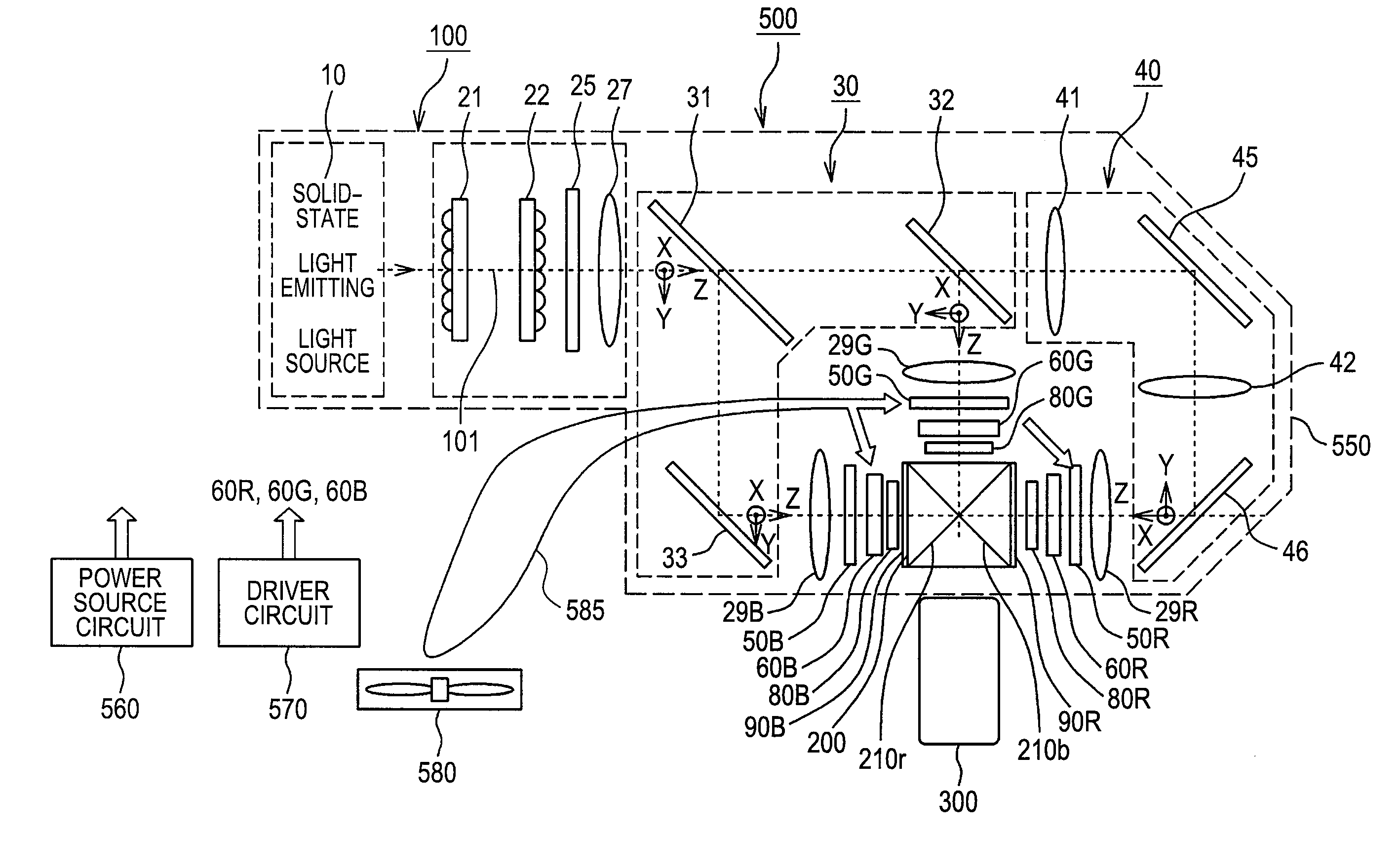
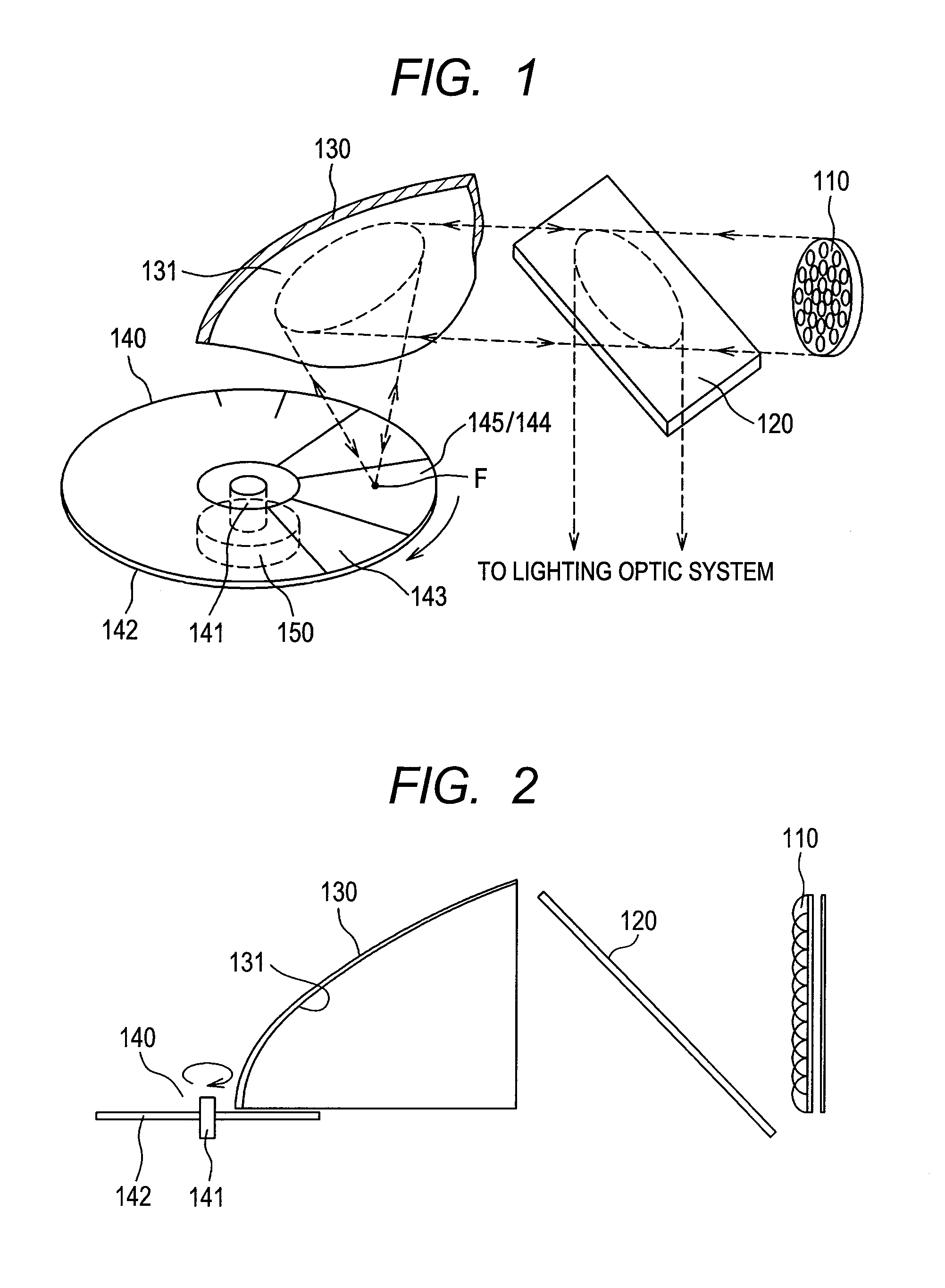
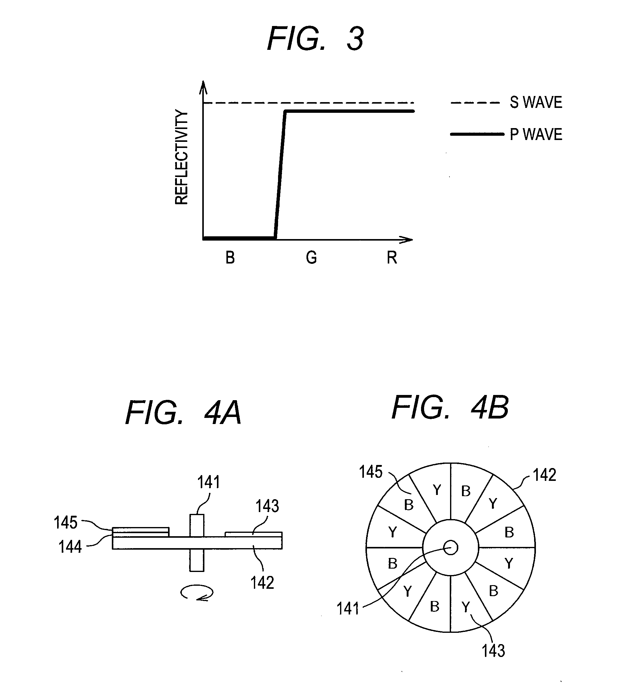
[0057]FIG. 1 attached herewith is a view for explaining the principle of the light source unit 10, according to an embodiment 1. As is apparent from the figure, that unit 10 comprises a semiconductor laser element group 110, aligning plural numbers of semiconductor laser elements or light emitting diodes, each emitting a light of blue color band (B-color), on an almost disc-like substrate, as a light emitting source of the solid-state elements, a separation mirror 120 disposed inclining at an angle of about 45 degree, facing to a laser beam emitting surface of the semiconductor laser element group 110 mentioned above, a reflection mirror (a reflector) 130 having a parabolic surface, for example, which is disposed at a position facing to that laser beam emitting surface of the semiconductor laser element group 110 mentioned above, a disc (or wheel) member 140 rotating round in the vicinity of a focus point (F) of that reflection mirror, and a driving means for rotationally drive that...

embodiment 2

[0078]In the embodiment 1 mentioned above, although description was made on the case where the base member 142 building up the disc (or wheel) member 140 mentioned above is basically the reflection surface, however next thereto, as an embodiment 2, detailed description will be made on the case where a permeable material is used for that base member 142′, hereinafter. But, in the explanation given below, the reference numerals, which are same to those in the embodiment 1 mentioned above, indicate the constituent elements same to the above.

[0079]As is shown in FIG. 11 attached, in the light source unit (i.e., the solid-state light source device) according to the embodiment 2, without applying the separation mirror 120 mentioned above, but in the place thereof is provided a similar reflection mirror (or reflector) (hereinafter, being called a “second reflection mirror 130′”), below the reflection mirror (or reflector) 130 (hereinafter, being called the “first reflection mirror (or refl...


PUM


Abstract

A solid-state light source device, enabling to build up with using solid-state elements, and having the structure suitable to be applied as a light source for a projection-type display apparatus, comprises a solid-state light source unit 10 for emitting excitation light therefrom, a reflection mirror (or reflector) 130 made of a parabolic surface, for condensing the excitation light from the solid-state light source to be point-like, and a disc-like (or wheel) member 140, repeating reflection/scattering or transmission/scattering of the excitation light and conversion of the excitation light, alternately, in vicinity of a focus point of the excitation light, which is condensed to be point-like by the reflection mirror (or reflector), wherein the excitation light (B-color) reflected/or scattered by that disc-like (or wheel) member and fluorescence light (Y-color), wavelength of which is converted, is taken on a same optical path, by means of the reflection mirror (or reflector) 130 or a second reflection mirror (or reflector) 130′, and thereby outputting a white color light emitting from a point-like light source.

Description

[0001]This application relates to and claims priority from Japanese Patent Application No. 2010-028771 filed on Feb. 12, 2010, the entire disclosure of which is incorporated herein by reference.BACKGROUND OF THE INVENTION[0002]The present invention relates to a solid-state light source device applying a solid-state element, such as, a light emitting diode or a semiconductor laser, etc., as a light source therein, attracting attentions thereon as a light source being superior in energy saving, and in particular, it relates to a solid-state light source device suitable for a projection-type display apparatus, modulating an intensity of the light from a light source depending on a video signal, by means of a light-transmission type or reflection type liquid crystal panel or a digital mirror device (DGD), which is built up with plural numbers of micro mirrors aligned, thereby projecting an optical image formed, enlargedly.[0003]In recent years, as a lightening apparatus is used a light ...

Claims


Application Information

Patent Timeline
Patent Type & Authority Applications(United States)
IPC IPC(8): G03B21/14F21V9/00F21V7/00F21V9/16
CPCG03B21/20G03B21/204G03B21/142G03B21/208G03B21/2066
Inventor HIRATA, KOJIIKEDA, HIDEHIROKIMURA, NOBUYUKI
Owner MAXELL HLDG LTD
Why Eureka
Try Eureka