
Disposable Reamer

a reamer and reamer technology, applied in the field of reamer devices, can solve the problems of reducing the effectiveness of cutting tools, restricting the flow of debris, and clogging of teeth openings, etc., and achieves the effects of improving cutting efficiency, enhancing the reamer's increased tissue removal efficiency, and increasing the cutting surface area

Active Publication Date: 2011-08-18
WILSON GREATBATCH LTD
View PDF4 Cites 48 Cited by
  • Summary
  • Abstract
  • Description
  • Claims
  • Application Information

AI Technical Summary

Benefits of technology

[0015]The reamer of the present invention comprises a reamer assembly that connects to a reamer shaft. The reamer assembly further comprises a partially hemispherical shell designed with a series of rib portions that extend longitudinally from a central region about an apex of the shell. These rib portions are attached to a reamer driver interface that provides stability to the reamer assembly. A gap is provided between adjacent rib portions. This feature allows for the unobstructed passage of tissue and contributes to the improved cutting efficiency.
[0016]Each rib portion is further designed with a leading edge portion and a trailing edge portion. These leading and trailing edge portions extend longitudinally along opposing sides of each rib. The leading edge portion comprises a tissue and bone cutting surface that extends along a region of the rib portion. This extended tissue cutting surface increases the tissue cutting surface area which enhances the reamer's increased tissue removal efficiency. The tissue cutting surface further incorporates various cutting surface textures, such as a serrated edge, or razor thin edge, among others.
[0017]Furthermore, the tissue cutting surface can be bent, thereby providing a customizable rake angle that increases the tissue and bone cutting efficiency of the present reamer.
[0018]Therefore, the features of the reamer of the present invention provide for a reamer with increased tissue removal efficiency as compared to the prior art. Thus, a reduction in surgical procedure time, patient trauma, infection risk and associated medical costs is achievable.

Problems solved by technology

In addition, the relatively small tissue cutting opening of the prior art restricts the flow of debris.
Many problems are associated with these traditional reamer designs.
One is that the prior art teeth openings tend to clog with use.
The teeth openings clog, thus preventing additional tissue removal and reduce the effectiveness of the cutting tool.
Removing and reinserting the reamer increases procedure time and further exposes a person to the possibility of infection.
Another problem is that the tissue cutting surface has a relatively small surface area.
Furthermore, these prior art designs limit the ability of a tool design to incorporate additional tissue cutting surface features.
These prior art design limitations impede tissue removal efficiency.
Thus, the use of these prior art reamers results in prolonged surgical times, prolonged patient trauma, increased risk of infection and increased medical costs.

Method used


Image

  • Disposable Reamer
  • Disposable Reamer
  • Disposable Reamer

Examples


Embodiment Construction

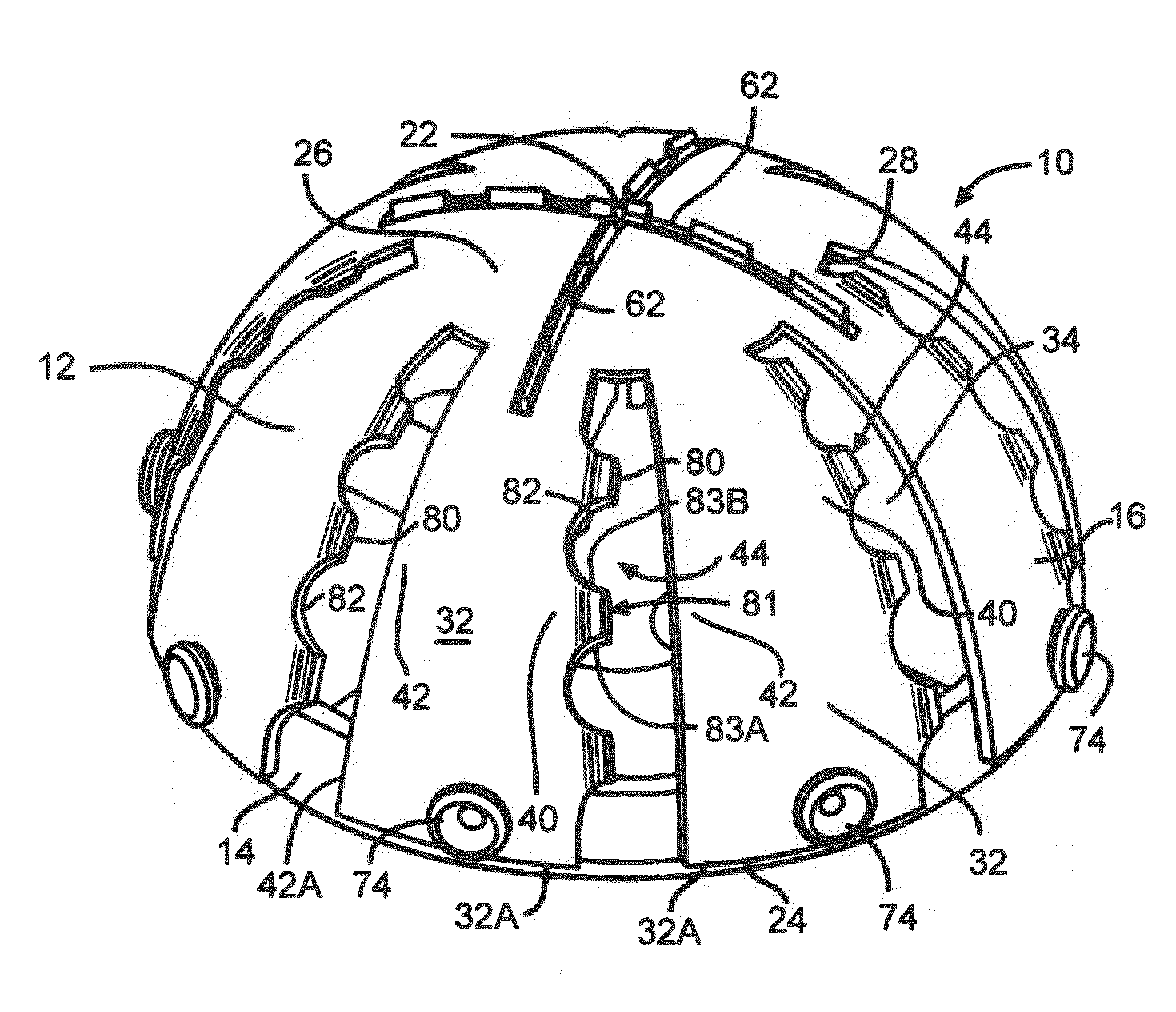
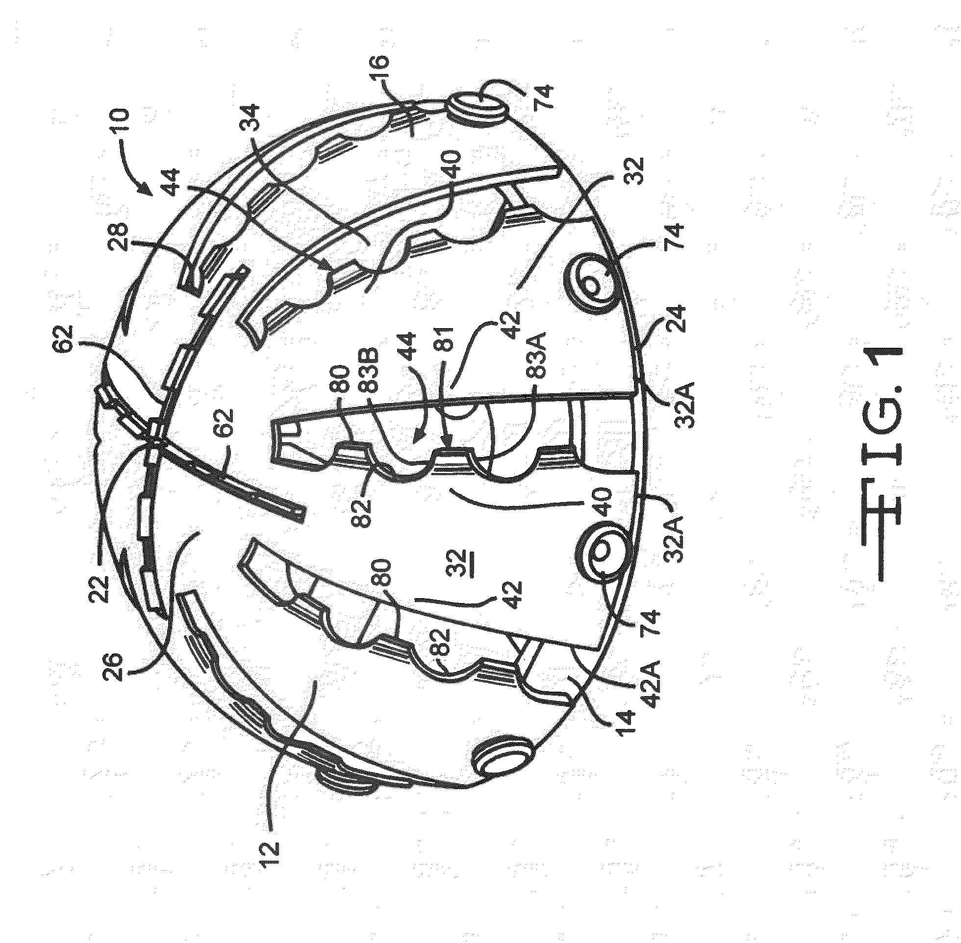
[0030]Now turning to the figures, FIG. 1 illustrates a preferred embodiment of a reamer 10 of the present invention. As illustrated, the reamer 10 preferably comprises a cutting shell 12 that is in communication with a reamer drive interface 14. The reamer drive interface 14 provides strength and rigidity to the cutting shell 12. In addition, the reamer drive interface 14 provides a means for connecting a drive shaft (not shown) to the reamer 10. Thus, when the reamer 10 is connected to the drive shaft (not shown) a physician can operate the reamer 10 from a distal location. The reamer 10 can either be manually operated or, alternatively, be connected to a motor (not shown) to provide power assisted tissue removal.

[0031]As illustrated in FIG. 1, the cutting shell 12 is generally of a hemispherical shape. The shell 12 further comprises an exterior surface 16, an interior surface 18 (FIG. 8) and a wall thickness 20 therebetween (FIG. 8). In a preferred embodiment, the wall thickness 2...


PUM


Abstract

A disposable acetabular reamer designed to improve tissue removal efficiency is described. The reamer device comprises a reamer cutting shell and a reamer driver interface. The reamer cutting shell has a hemispherical structure with a plurality of spaced apart rib portions that extend from a central region located about an apex of the shell. A tissue cutting surface further extends along a longitudinal leading edge, trailing edge or both leading and trailing rib portions. The tissue cutting surface further comprises a series of alternating cutting teeth and notches which are bent at a rake angle.

Description

CROSS-REFERENCE TO RELATED APPLICATIONS[0001]This application claims priority from U.S. Provisional Patent Application Ser. No. 61 / 303,699, filed Feb. 12, 2010.1. FIELD OF THE INVENTION[0002]The present invention relates to the art of orthopedic cutting devices, more particularly, to a reamer device designed to remove tissue from the acetabulum.2. PRIOR ART[0003]Reamers are devices intended to remove tissue and bone from the human body. Specifically, the reamer of the present invention is designed to remove tissue from the cotyloid cavity of the acetabulum in preparation for the insertion of a hip joint by a prosthetic cup.[0004]In general, acetabular reamers are constructed with a continuous partially hemispherical surface. This partial hemispherical structure is ideally suited to create a cavity in which to fit a prosthetic cup. Prosthetic cups generally have a curved exterior surface that is inserted into the cotyloid cavity.[0005]A series of discrete tissue cutting openings are ...

Claims


Application Information

Patent Timeline
IPC IPC(8): A61B17/00
CPCA61B17/1666
Inventor WHITE, PATRICK M.VICTOR, GARY
Owner WILSON GREATBATCH LTD
Features
  • Generate Ideas
  • Intellectual Property
  • Life Sciences
  • Materials
  • Tech Scout
  • Unparalleled Data Quality
  • Higher Quality Content
  • 60% Fewer Hallucinations
Learn More