Track guiding system

a track and guiding technology, applied in the direction of transportation and packaging, manufacturing tools, roads, etc., can solve the problems of rollers jumping when they encounter non-smooth difficult to make two beams and plate attachments that have the same dimensions and tolerances, and uneven connections between adjacent beams

Active Publication Date: 2011-08-25
NAT OILWELL VARCO LP
View PDF26 Cites 21 Cited by
  • Summary
  • Abstract
  • Description
  • Claims
  • Application Information

AI Technical Summary

Benefits of technology

[0011]The following presents a simplified summary of the invention in order to provide a basic understanding of some aspects of the invention. This summary is not an exhaustive overview of the invention. It is not intended to...

Problems solved by technology

Connections between the plates on adjacent beams are typically not smooth, particularly because it is difficult to make two beams and plate attachments that have the same dimensions and tolerances.
Rollers tend to jump when they encounter these non-smooth connections.
Wobbling, sliding or jumping of the rollers will adversely affect the stability of the top drive as the top dr...

Method used


Image

  • Track guiding system
  • Track guiding system
  • Track guiding system

Examples


Embodiment Construction

[0030]Various illustrative embodiments of the invention are described below. In the interest of clarity, not all features of an actual implementation are described in this specification. It will of course be appreciated that in the development of any such actual embodiment, numerous implementation-specific decisions must be made to achieve the developers' specific goals, such as compliance with system-related and business-related constraints, which will vary from one implementation to another. Moreover, it will be appreciated that such a development effort might be complex and time-consuming, but would nevertheless be a routine undertaking for those of ordinary skill in the art having the benefit of this disclosure.

[0031]The present subject matter will now be described with reference to the attached figures. Various structures, systems and devices are schematically depicted in the drawings for purposes of explanation only and so as to not obscure the present disclosure with details ...


PUM


Abstract

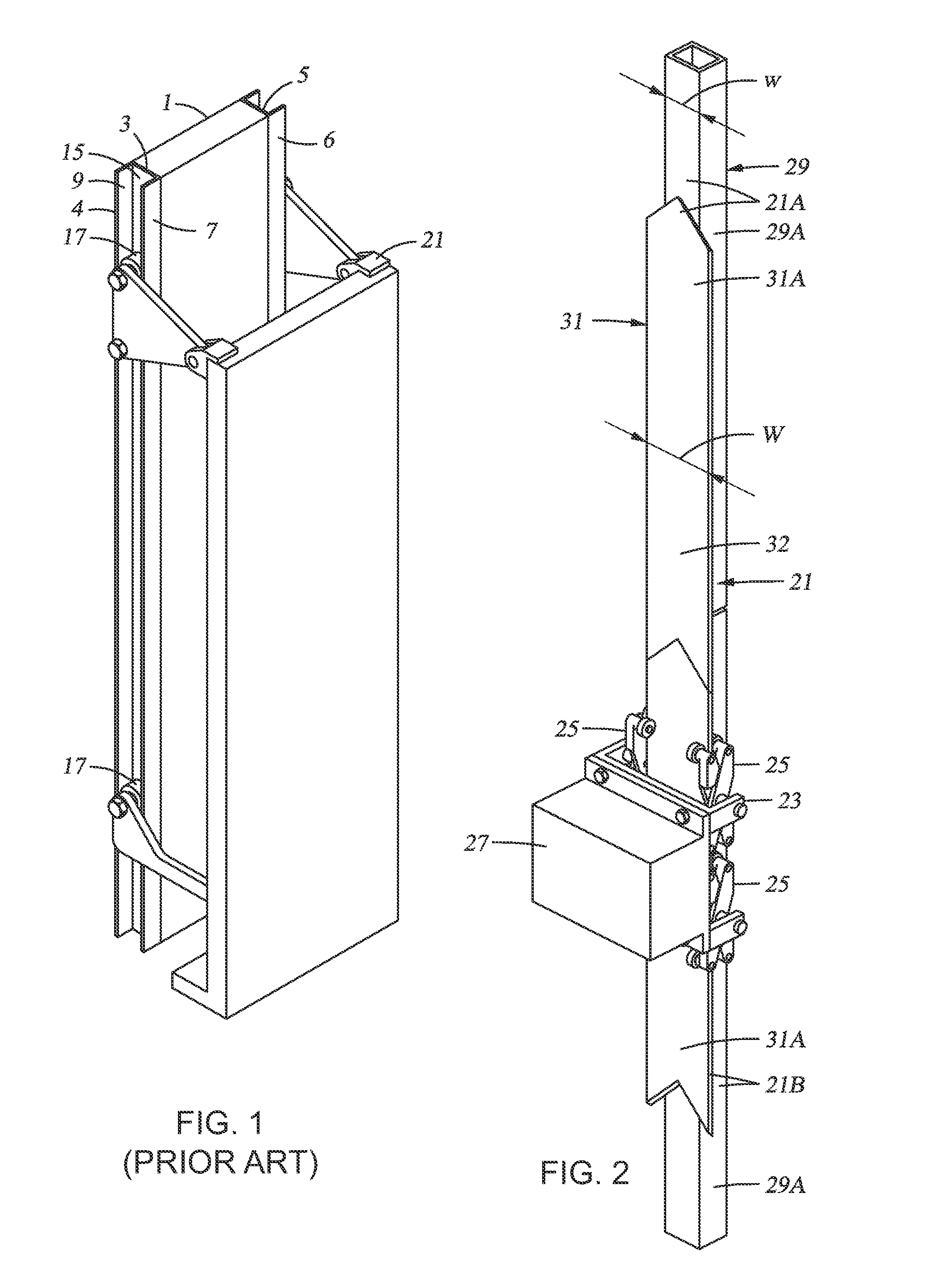
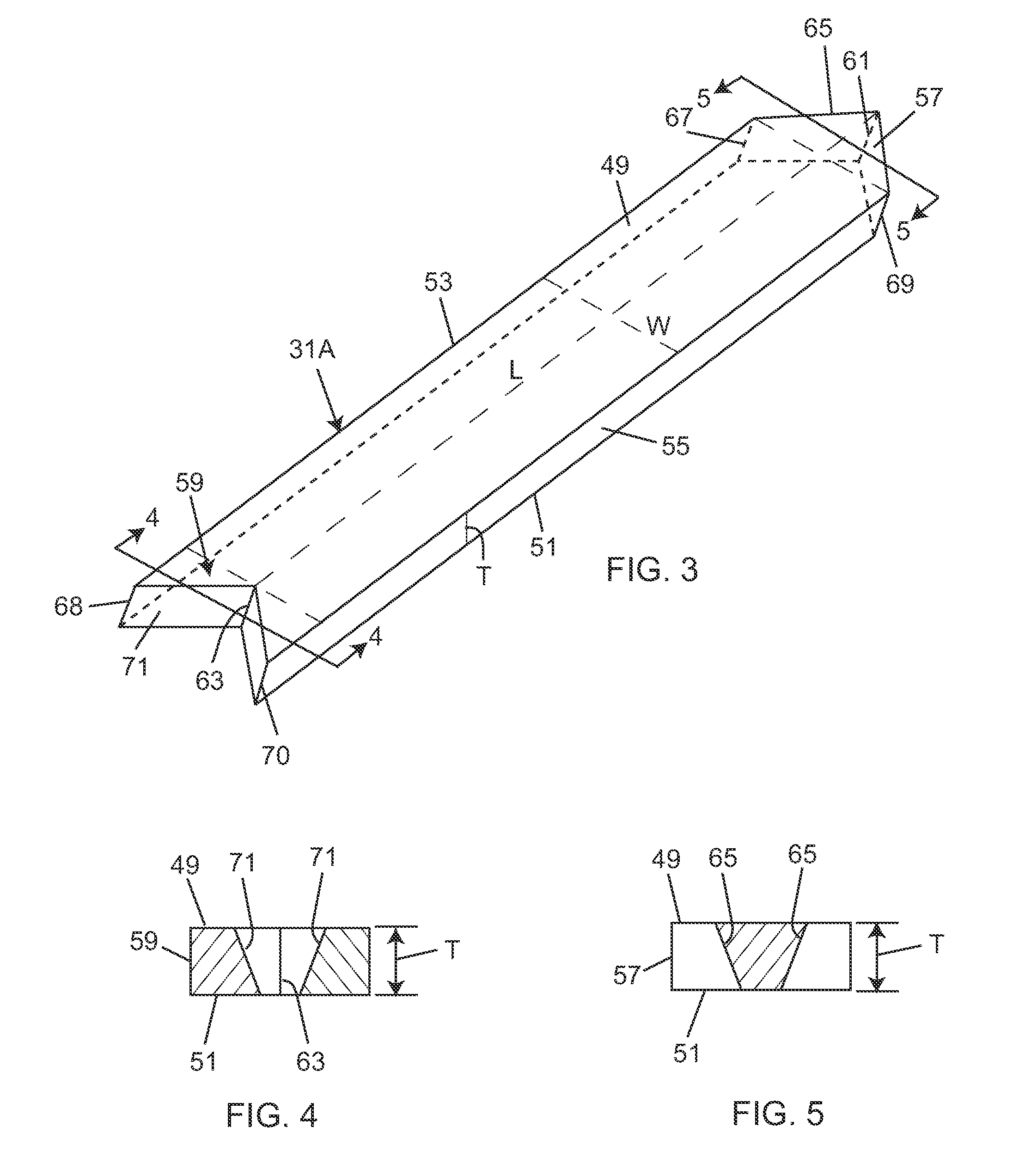
A track guiding system includes a track comprising a linear beam and a linear plate operatively coupled to the linear beam. The linear plate has opposing first and second surfaces separated by a first distance and opposing first and second edges separated by a second distance. A first compound edge roller and a second compound edge roller are disposed adjacent to the first and second edges of the linear plate, respectively, for travel along the first and second edges of the linear plate. Each of the first and second compound edge rollers include a first roller element adjacent to the first surface of the linear plate and a second roller element adjacent to the second surface of the linear plate. A carriage is coupled to the first and second compound edge rollers.

Description

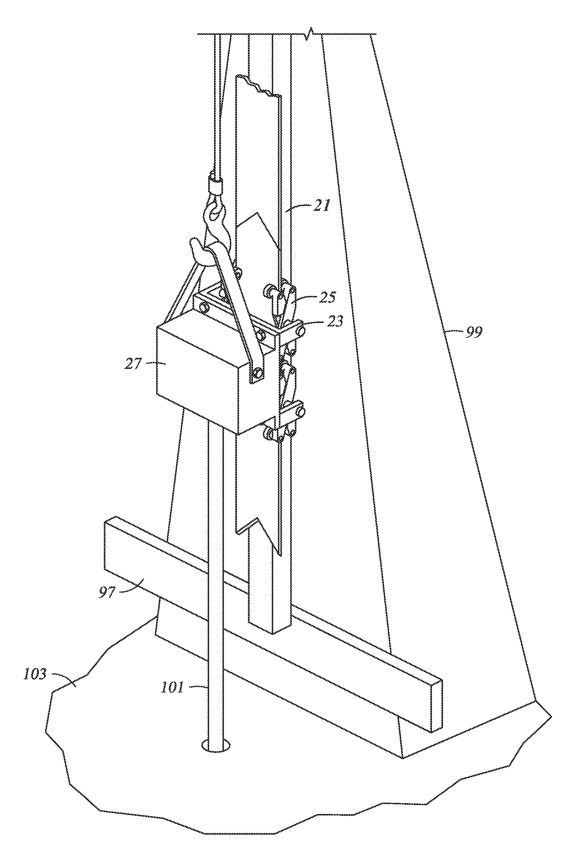
BACKGROUND OF THE INVENTION[0001]1. Field of the Invention[0002]The present disclosure relates generally to track guiding systems for guiding travel of an object along a defined path, and more particularly to a track guiding system for guiding travel of an object along a vertical path.[0003]2. Description of the Related Art[0004]A top drive is an example of a device requiring guided travel along a defined path. In this case, the defined path is a vertical path. The top drive is used to rotate a drill string from the top of the drill string, typically while the drill string is in a borehole. The top drive includes at least one motor and a gear system. The motor is coupled to the gear system, and the gear system is connected to a short pipe, which is in turn attached to the top of the drill string. The top drive is suspended on a hook at the end of a traveling block. The traveling block itself is suspended by cables from the top of a derrick. The traveling block moves up and down the ...

Claims


Application Information

Patent Timeline
IPC IPC(8): E21B4/00B61B13/04B61B13/00
CPCB61B15/00E21B19/24E21B15/00
Inventor MARICA, ADRIANMIHAI, IONESCU
Owner NAT OILWELL VARCO LP
Why Eureka
Try Eureka