Vehicle power transmission device

a technology of power transmission device and bearing, which is applied in the direction of electric propulsion mounting, gearing, transportation and packaging, etc., can solve the problems of deterioration of durability of the first bearing, difficulty in providing a sufficient amount of lubricant oil from the inner circumferential, and difficulty in ensuring the support so as to achieve the effect of reducing cost and ensuring the stiffness of the second power transmission member

Active Publication Date: 2011-08-25
TOYOTA JIDOSHA KK +1
View PDF7 Cites 15 Cited by
  • Summary
  • Abstract
  • Description
  • Claims
  • Application Information

AI Technical Summary

Benefits of technology

[0015]According to a vehicle power transmission device recited in the first aspect of the invention, since the portion of a circular disc gear portion protruded to the second power transmission member facing the first bearing is provided with the annular inner circumferential guide protruding portion for guiding to the first bearing the lubricant oil that passes through the second bearing arranged to the inner circumferential side of the first bearing for lubrication, that enters into the gap between the second bearing and the gear portion, and that travels to the outer circumferential side due to the centrifugal force, the lubricant oil used for the lubrication of the second bearing is sufficiently guided to the first bearing by the inner circumferential guide protruding portion even if the first bearing rotates at a high speed and, therefore, the durability of the first bearing can be restrained from deteriorating due to insufficient lubrication even if the first bearing is arranged to radially overlap with the second bearing.
[0016]According to the vehicle power transmission device recited in the second aspect of the invention, since the inner circumferential guide protruding portion of the second power transmission member protrudes toward the first bearing at the inner circumferential side than the inner circumferential end portion of the support wall for fitting and attaching the outer ring of the first bearing from the facing portion in the first bearing of the gear portion to be closer to the first bearing than the one end surface of the inner circumferential end portion on a gear portion side, the lubricant oil passing through the second bearing and traveling to the outer circumferential side due to the centrifugal force is guided toward the first bearing by the inner circumferential guide protruding portion without being discharged to the outer circumferential side from the gap between the inner circumferential end portion of the support wall and the gear portion and, therefore, the lubricant oil can be supplied to the first bearing in substantially the same amount as the amount supplied to the second bearing.
[0017]According to the vehicle power transmission device recited in the third aspect of the invention, since at one end portion of the inner circumferential end portion of the support wall toward the gear portion, an outer circumferential guide protruding portion for guiding the lubricant oil to the first bearing is formed that protrudes to the inner circumferential side, the lubricant oil passing through the second bearing and traveling to the outer circumferential side due to the centrifugal force is prevented by the outer circumferential guide protruding portion from moving toward the gap between the inner circumferential end portion of the support wall and the gear portion, the lubricant oil can be restrained from entering into the gap between the inner circumferential end portion of the support wall and the gear portion to be discharged to the outer circumferential side without being supplied to the first bearing. Therefore, the lubricant oil can be supplied to the first bearing in substantially the same amount as the amount supplied to the second bearing.
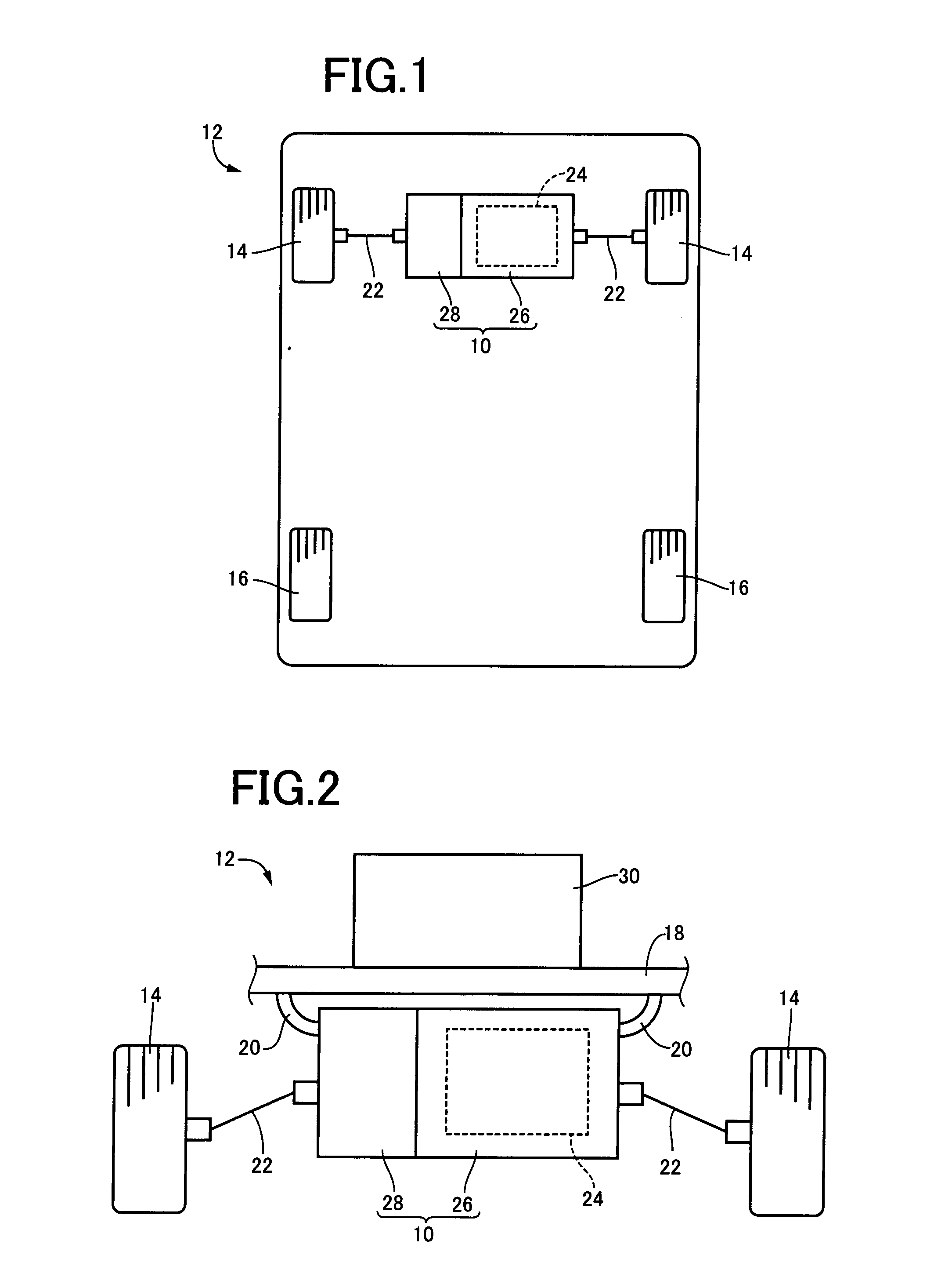
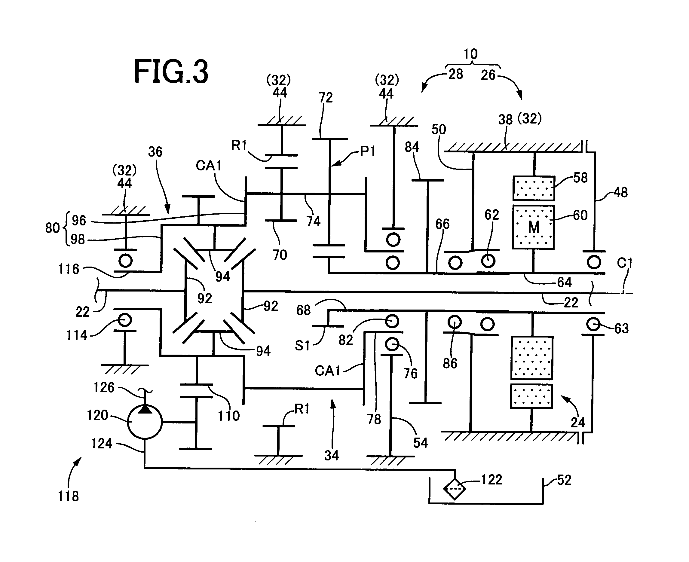
[0018]According to the vehicle power transmission device recited in the fourth aspect of the invention, since a speed reducer that reduces output rotation of an electric motor disposed on the shaft center and a differential gear device that distributes the output rotation of the speed reducer to a pair of left and right axles, wherein the first power transmission member is any one of a plurality of rotating elements of the speed reducer, and wherein the second power transmission member is an input shaft of the speed reducer disposed on an output shaft of the 
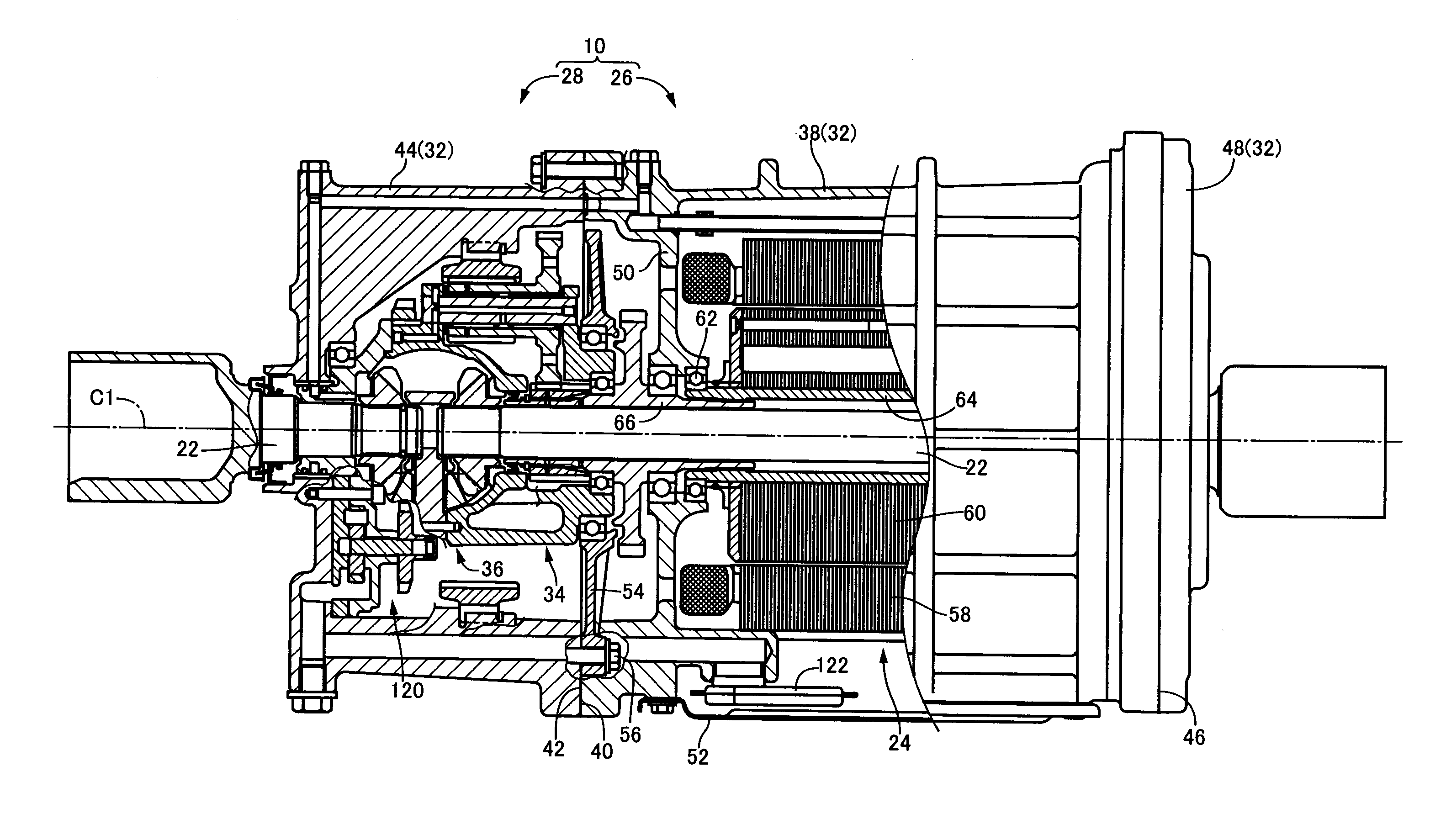
electric motor in a relatively non-rotatable manner, the lubricant oil is sufficiently supplied from the inner circumferential side to the first bearing disposed between the first power transmission device making up the speed reducer coupled to the subsequent stage of the electric motor that is relatively rotated at a high speed and the non-rotating support wall, therefore, the durability of the first bearing can be restrained from deteriorating due to insufficient lubrication even if the first bearing disposed between the two members that have a relatively large rotation difference is arranged to radially overlap with the second bearing.
[0019]According to the vehicle power transmission device recited in the fifth aspect of the invention, since the gear portion is a parking lock gear, it can sufficiently supply the lubricant oil to the first bearing simply by disposing the inner circumferential guide protruding portion at the parking lock gear that is the existing member without the need of newly disposing a special oil passage for supplying the lubricant oil to the first bearing and, therefore, the cost can be reduced.
[0020]According to the vehicle power transmission device recited in the sixth aspect of the invention, since the second power transmission member is rotatably supported via the second bearing and a third bearing on the both sides of the gear portion in the shaft center direction, the support stiffness of the second power transmission member can sufficiently be ensured.

Problems solved by technology

Although the second bearing is supplied with a sufficient amount of lubricant oil by supplying the lubricant oil from the inner circumferential side, since the lubricant oil passing through the second bearing is blown off to the outer circumferential side by a centrifugal force, it is difficult to supply a sufficient amount of the lubricant oil from the inner circumferential side to the first bearing arranged to overlap with the outer circumferential side of the second bearing.
Although it is conceivable to supply the lubricant oil to the first bearing from the outer circumferential side for this reason, it is difficult to supply a sufficient amount of the lubricant oil especially when the first bearing rotates at a high speed because the lubricant oil is repelled even if supplied from the outer circumferential side.
Therefore, the durability of the first bearing might deteriorate.

Method used


Image

  • Vehicle power transmission device
  • Vehicle power transmission device
  • Vehicle power transmission device

Examples


first embodiment

[0034]FIG. 1 conceptually depicts a configuration of a drive-train of a vehicle 12 including a vehicle driving device 10 according to one embodiment of the present invention. FIG. 2 conceptually depicts a configuration of the drive-train viewed from the back of the vehicle 12. In FIGS. 1 and 2, the vehicle 12 includes pairs of left and right front wheels 14 and rear wheels 16 respectively disposed on the front side and the rear side, and the vehicle driving device 10 fixed via a mount member 20 to a vehicle body 18 as depicted in FIG. 2 on the front side of the vehicle 12 to rotationally drive the pair of the front wheels 14 via a pair of left and right drive shafts (axles) 22.

[0035]The vehicle driving device 10 includes a driving portion 26 having an electric motor 24 functioning as a drive source of the vehicle 12 and transversally mounted on the vehicle 12, and a transaxle portion 28 functioning as a power transmission device that reduces and distributes the output rotation of th...


PUM


Abstract

A vehicle power transmission device includes: a first power transmission member including a cylindrical shaft end portion rotatably supported via a first bearing on an inner circumferential side of a non-rotating support wall; and a second power transmission member supported on the inside of the cylindrical shaft end portion via a second bearing radially overlapping with the first bearing by the cylindrical shaft end portion to be rotatable concentrically and relatively to the first power transmission member, the second power transmission member including a circular disc gear portion protruded to an outer circumferential side at a predetermined distance from the second bearing in a shaft center direction of the second power transmission member, at a portion facing the first bearing, the gear portion having an annular inner circumferential guide protruding portion for guiding to the first bearing a lubricant oil that passes through the second bearing for lubrication, that enters into a gap between the second bearing and the gear portion, and that travels to the outer circumferential side due to the centrifugal force.

Description

INCORPORATION BY REFERENCE[0001]The disclosure of Japanese Patent Application No. 2010-040535 filed on Feb. 25, 2010 including the specification, drawings and abstract is incorporated herein by reference in its entirety.BACKGROUND OF THE INVENTION[0002]1. Field of the Invention[0003]The present invention relates to a technique for enhancing durability of a bearing that rotatably supports a power transmission member included in a vehicle power transmission device.[0004]2. Description of the Related Art[0005]A vehicle power transmission device is known that has a transmission, a differential gear device, etc., for transmitting a drive force output from a drive source such as an engine and an electric motor to axles. The device is described in Japanese Laid-Open Patent Publication No. 2001-39179, for example. The transmission and the differential gear device include a plurality of power transmission members such as gears and rotation shafts each rotatably supported around a shaft cente...

Claims


Application Information

Patent Timeline
Patent Type & Authority Applications(United States)
IPC IPC(8): F16H57/04F16H48/06F16H48/20
CPCB60K1/00B60K2001/001F16C33/6659F16C2326/06F16C2361/65H02K7/116F16H57/0471F16H57/0476F16H57/0483F16H63/3416H02K7/006F16H57/0441F16H37/082
Inventor HARASHIMA, TERASUTANAKA, KOICHITESHIMA, ATSUSHISASAKI, YOSHIHIKOHAMAGUCHI, HIROSHI
Owner TOYOTA JIDOSHA KK
Why Eureka
Try Eureka