

Resonator element, resonator, oscillator, and electronic device
a resonator element and electronic device technology, applied in the field of resonator elements, resonators, oscillators, electronic devices, can solve the problems of over-etching of the resonator element at the tip end of the notch in the base, and achieve the effect of improving the impact resistance of the electronic device and improving the impact resistan
- Summary
- Abstract
- Description
- Claims
- Application Information
AI Technical Summary
Benefits of technology
Problems solved by technology
Method used
Image

Examples
first embodiment
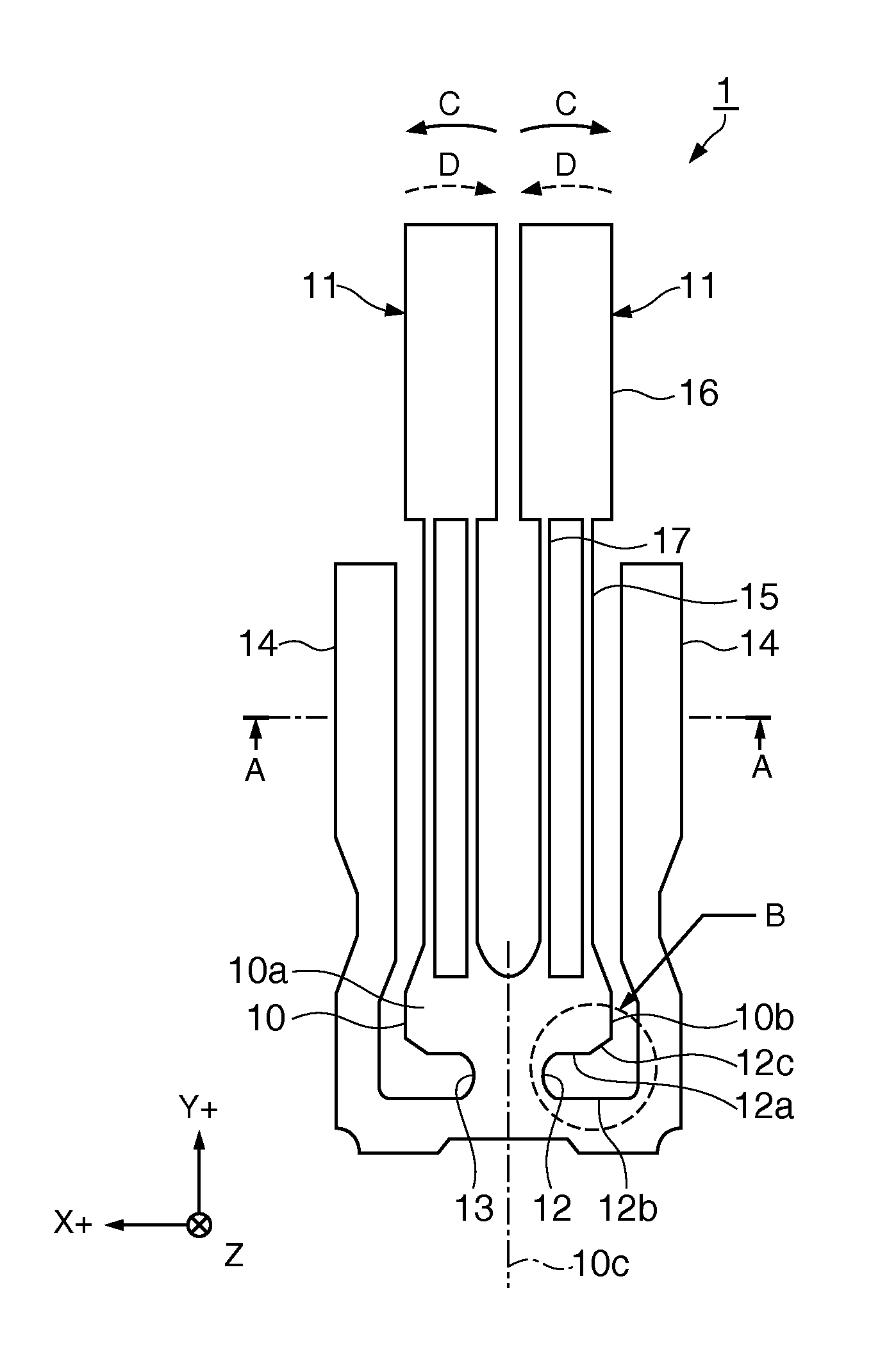
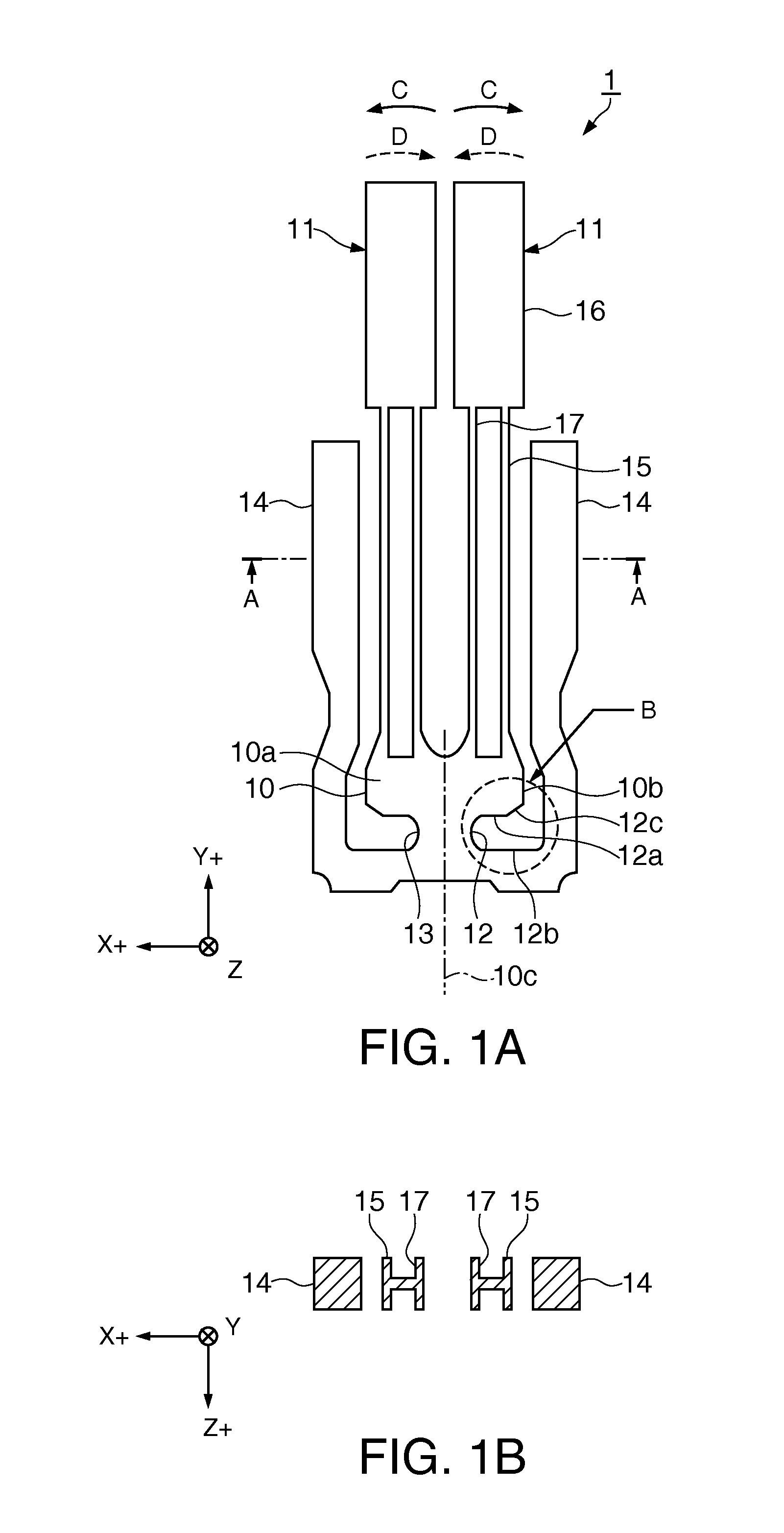
[0046]FIGS. 1A and 1B are schematic views showing a simplified configuration of a resonator element according to a first embodiment, in which FIG. 1A is a top view, and FIG. 1B is a cross-sectional view taken along the line IB-IB in FIG. 1A. FIG. 2 is an enlarged view of a “B” part in FIG. 1A.
[0047]As shown in FIGS. 1A and 1B, a quartz crystal resonator element 1 as a resonator element is a resonator element whose outer shape is formed by photolithographically etching (wet-etching) a Z plate which is cut, for example, from quartz crystal ore, at predetermined angles with respect to the mutually orthogonal X, Y, and Z axes which are the crystal axes of a quartz crystal. In this embodiment, etching is performed using an etching solution containing hydrofluoric acid.
[0048]Here, the Z plate means a plate whose cutting surface (principal surface 10a) is approximately orthogonal to the Z axis. Thus, the Z plate also includes a plate whose principal surface 10a orthogonal to the Z axis is ...
second embodiment
[0078]FIGS. 4A and 4B are schematic views showing a simplified configuration of a resonator element according to a second embodiment used in an electronic device according to the invention, in which FIG. 4A is a top view, and FIG. 4B is a cross-sectional view taken along the line IVB-IVB in FIG. 4A. FIG. 5 is an enlarged view of a “F” part in FIG. 4A.
[0079]The same portions as the first embodiment will be denoted by the same reference numerals, and description thereof is omitted. In the following description, only the portions different from those of the first embodiment will be described.
[0080]As shown in FIGS. 4A and 4B, a quartz crystal resonator element 2 as a resonator element is different from that of the first embodiment, in that the positive X-axis notch 12 and the negative X-axis notch 13 are shaped differently.
[0081]As shown in FIG. 5, the base 10 of the quartz crystal resonator element 2 has a slope portion 12d which is disposed between an outer circumference 10b of the b...
third embodiment
[0099]Next, a resonator having the quartz crystal resonator element described above will be described as a third embodiment.
[0100]FIGS. 7A and 7B are schematic views showing a simplified configuration of a resonator according to a third embodiment, in which FIG. 7A is a top view, and FIG. 7B is a cross-sectional view taken along the line VIIB-VIIB in FIG. 7A.
[0101]As shown in FIGS. 7A and 7B, a quartz crystal resonator 5 as a resonator includes the quartz crystal resonator element 1 of the first embodiment and a package 80 that accommodates the quartz crystal resonator element 1.
[0102]The package 80 includes a package base 81, a seam ring 82, a cover 85, and the like.
[0103]The package base 81 has a recess so that the quartz crystal resonator element 1 can be accommodated therein, and connection pads 88 connected to the mount electrodes (not shown) of the quartz crystal resonator element 1 are provided in the recess.
[0104]The connection pads 88 are connected to wirings inside the pac...
PUM
 Abstract
Description
Claims
Application Information