
High tortuosity diffusion medium

a diffusion medium and high-temperature technology, applied in the field of fuel cells, can solve the problems of low transport resistance for reactant access and water removal, low transport resistance of state-of-the-art materials, and limited performance of automotive fuel cells using current diffusion media, etc., to improve performance, optimize water management, and improve fuel cell operation robustness

Inactive Publication Date: 2011-08-25
GM GLOBAL TECH OPERATIONS LLC
View PDF2 Cites 21 Cited by
  • Summary
  • Abstract
  • Description
  • Claims
  • Application Information

AI Technical Summary

Benefits of technology

[0009]Concordant and congruous with the present invention a diffusion medium adapted to optimize water management while also improving the performance and the operation robustness of the fuel cell has been discovered.

Problems solved by technology

In contrast to that, wet operating conditions (where the reactant gases are saturated with vapor and condensation can occur) provide water for membrane humidification in abundance, and low transport resistances for reactant access and water removal are required.
Furthermore, the transport resistance of state-of-the-art materials is usually very low.
The performance of automotive fuel cells using such current diffusion media is limited because reactant streams are often subsaturated with water vapor at the cell inlet but get increasingly saturated with vapor up to the point of condensation along the flow direction at the outlet.
The unresolved problem, hence, is to provide a fuel cell diffusion medium with varying transport resistance across the active area exhibiting high transport resistance at the cell inlet for water vapor retention at the membrane and low transport resistance at the outlet where water has to be removed effectively.
Since the layer thickness in fuel cell applications is limited due to technical restrictions, increasing the transport resistance by increasing the layer thickness is usually not possible.
Hence, decreasing the effective diffusivity is required.
Analytical studies have shown that porosity needs to be significantly reduced to show an effect, and furthermore the degree to which porosity can be reduced in current materials (which are random porous media based on carbon fiber papers with particulate coating made from carbon black) is limited, too.

Method used


Image

  • High tortuosity diffusion medium
  • High tortuosity diffusion medium
  • High tortuosity diffusion medium

Examples


Embodiment Construction

[0023]The following detailed description and appended drawings describe and illustrate various exemplary embodiments of the invention. The description and drawings serve to enable one skilled in the art to make and use the invention, and are not intended to limit the scope of the invention in any manner.

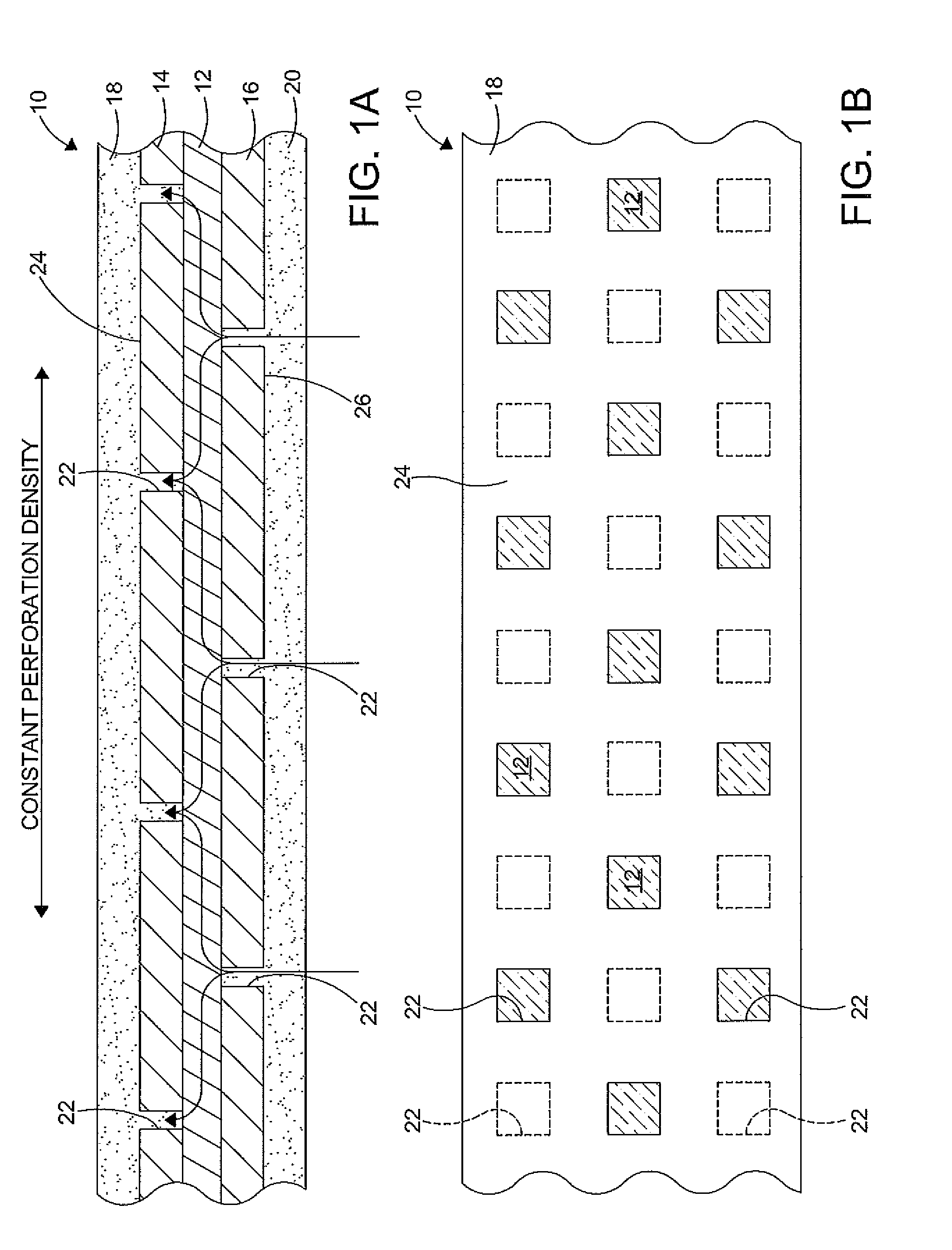
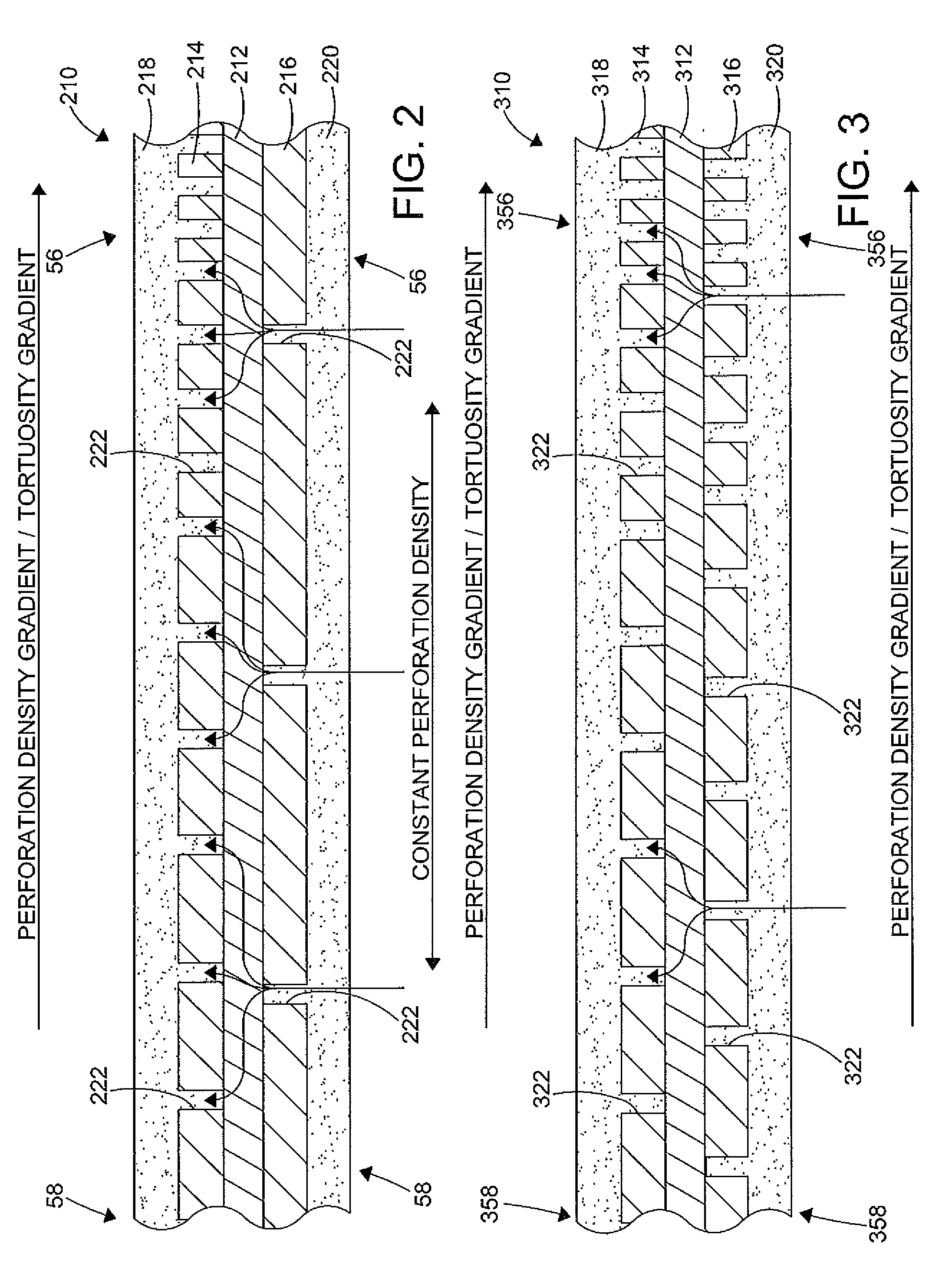
[0024]FIGS. 1a and 1b illustrate a diffusion medium 10 according to an embodiment of the invention. The diffusion medium 10 includes a porous spacer layer 12, a first perforated layer 14, a second perforated layer 16, a first microporous layer 18, and a second microporous layer 20. It is understood that a thickness of the diffusion medium 10 and layers 12, 14, 16, 18, 20 thereof may vary based on a desired performance of a fuel cell in which the diffusion medium 10 is used. Based on the above description of the concept of tortuosity, the thickness of the porous spacer layer 12 should be minimized to maximize tortuosity (and minimize the through-plane electrical resistance) of the dif...


PUM

PropertyMeasurementUnit
electrically conductiveaaaaaaaaaa
densityaaaaaaaaaa
perforation densityaaaaaaaaaa

Abstract

A diffusion medium for use in a PEM fuel cell including a porous spacer layer disposed between a plurality of perforated layers having variable size and frequency of perforation patterns, each perforated layer having a microporous layer formed thereon, wherein the diffusion medium is adapted to optimize water management in and performance of the fuel cell.

Description

FIELD OF THE INVENTION[0001]The invention relates to a fuel cell, and more particularly to a diffusion medium for a fuel cell adapted to optimize water management within the fuel cell, the diffusion medium including a porous spacer layer, a plurality of perforated layers having perforations of variable size, frequency and arrangement, and a plurality of microporous layers, wherein the microporous layers and perforated layers are disposed on the porous spacer layer.BACKGROUND OF THE INVENTION[0002]Fuel cells are increasingly being used as a power source for electric vehicles and other applications. In proton exchange membrane (PEM) fuel cells, hydrogen is supplied to an anode catalytic electrode of the fuel cell and air with oxygen as an oxidant is supplied to a cathode catalytic electrode of the fuel cell. The electrochemical reaction that occurs between the reactant gases in the fuel cell consumes the hydrogen at the anode side and the oxygen at the cathode side and produces produc...

Claims


Application Information

Patent Timeline
Patent Type & Authority Applications(United States)
IPC IPC(8): H01M8/04
CPCH01M8/0234H01M8/0245Y02E60/50H01M2008/1095H01M8/0247
Inventor WIESER, CHRISTIANNICOTERA, PAUL D.
Owner GM GLOBAL TECH OPERATIONS LLC
Learn More