Installation error estimating device and installation error estimating method
Inactive Publication Date: 2011-08-25
PANASONIC CORP
View PDF8 Cites 10 Cited by
Summary
Abstract
Description
Claims
Application Information
AI Technical Summary
This helps you quickly interpret patents by identifying the three key elements:
Problems solved by technology
Method used
Benefits of technology
Benefits of technology
[0015]The present invention is capable of enabling error-free, high-precision positioning to be achieved with simple installation. That is to say, when a tag reader is installed at a predetermined position and performs high-precision positioning, special installation structure, parts, and the like for the tag reader can be made unnecessary, and simple installation can be made possible that does not require a high degree of expertise in installation and measurement on the part of installation engineers, without sacrificing high-precision of positioning.
Problems solved by technology
Although a potential demand for high-precision position management by means of wireless tags has hitherto become evident from the standpoint of distribution and security management and the like, a necessary level of measurement precision has not been attained, and therefore such position management has not become widely established.
Method used
Image
Click on the blue label to locate the original text in one second.
Reading with bidirectional positioning of images and text.
Examples
embodiment 1
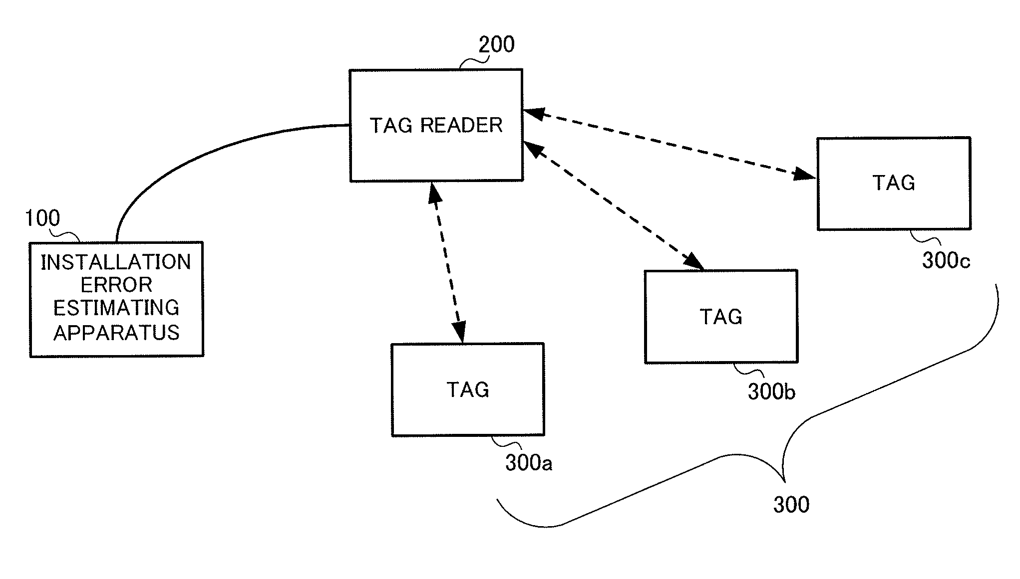
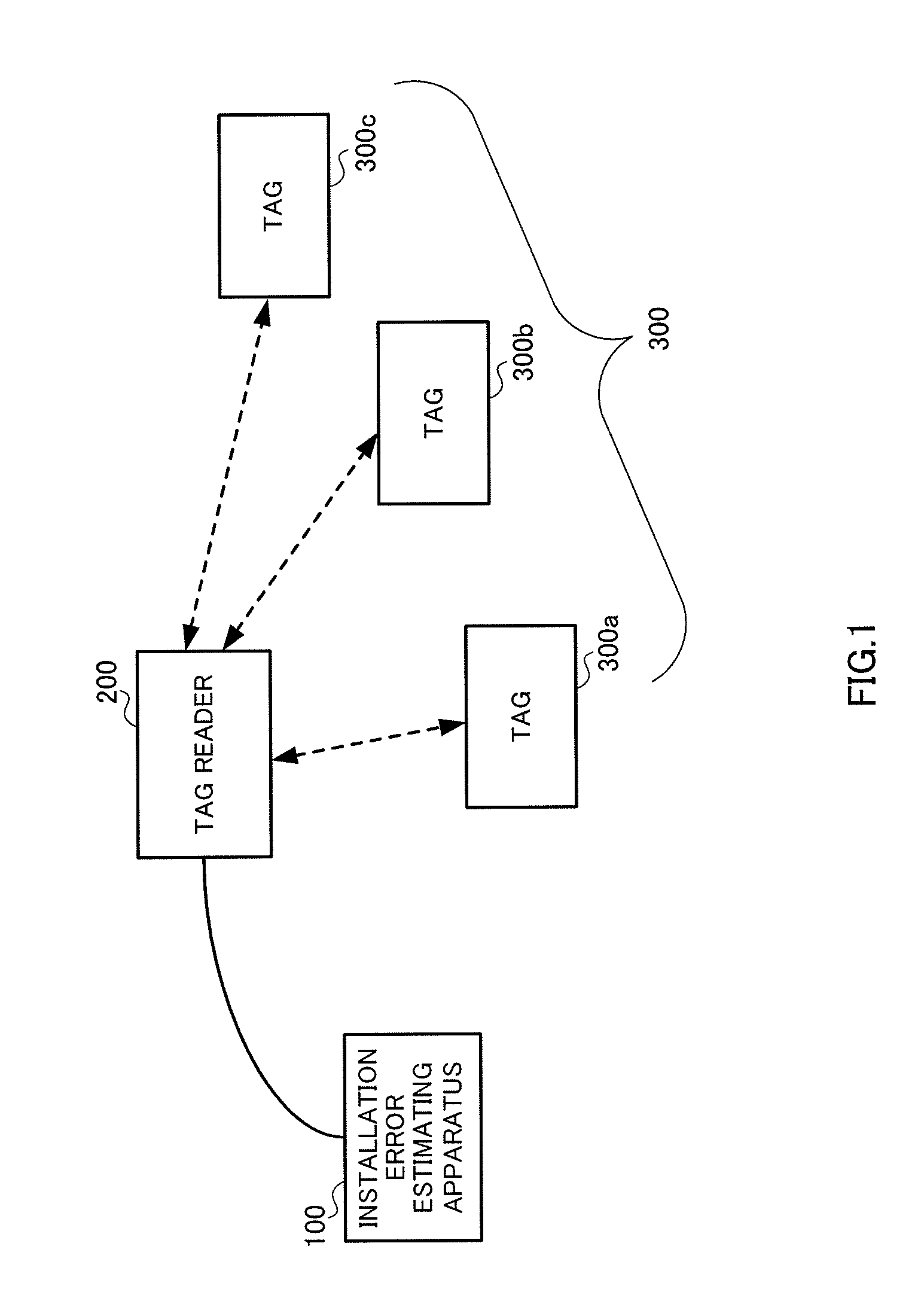
[0050]FIG. 1 is a configuration diagram of a UWB positioning system that includes an installation error estimating apparatus according to Embodiment 1 of the present invention.
[0051]The system shown in FIG. 1 has installation error estimating apparatus 100, tag reader 200, and wireless tags 300. In FIG. 1, three wireless tags 300a, 300b, and 300c are shown as wireless tags 300. Installation error estimating apparatus 100 estimates the installation position of tag reader 200. The configuration and operation of installation error estimating apparatus 100 will be described in detail later herein. Tag reader 200 performs position detection for wireless tags 300 by means of single-point positioning. Wireless tags 300 are UWB tags, for example.
[0052]For example, a UWB positioning system sequentially detects wireless tag 300 positions by having wireless tags 300 attached to a person or object and performing radio communication with tag reader 200. Consequently, a UWB positioning system can...
embodiment 2
[0201]Embodiment 2 is a case in which, when a tag reader is installed, a wireless tag is placed peripheral to the tag reader (at an observation point), the position of the wireless tag is measured, tag reader installation error is estimated based on obtained observation data, and the estimated installation error is evaluated.
[0202]This embodiment will now be described using FIG. 21 through FIG. 24.
[0203]FIG. 21 is a block diagram showing the configuration of an installation error estimating apparatus according to Embodiment 2 of the present invention. This installation error estimating apparatus 700 has a similar basic configuration to installation error estimating apparatus 100 corresponding to Embodiment 1 shown in FIG. 4, and configuration elements in FIG. 21 identical to those in FIG. 4 are assigned the same reference codes as in FIG. 4 and descriptions thereof are omitted here.
[0204]Installation error estimating apparatus 700 shown in FIG. 21 has convergence determination secti...
embodiment 3
[0242]Embodiment 3 is a case in which, in addition to the provisions of Embodiment 1, a position for newly placing a wireless tag as an observation object is further recommended if estimated installation error does not satisfy a convergence condition.
[0243]This embodiment will now be described using FIG. 25 through FIG. 28.
[0244]FIG. 25 is a block diagram showing the configuration of an installation error estimating apparatus according to Embodiment 3 of the present invention. This installation error estimating apparatus 800 has a similar basic configuration to installation error estimating apparatus 100 corresponding to Embodiment 1 shown in FIG. 4 and installation error estimating apparatus 700 corresponding to Embodiment 2 shown in FIG. 21. Configuration elements in FIG. 25 identical to those in FIG. 4 and FIG. 21 are assigned the same reference codes as in FIG. 4 and FIG. 21, and descriptions thereof are omitted here.
PUM
Abstract
The installation error estimating device is capable of enabling error-free high-precision positioning with simple installation. The device has a predicted pattern acquisition unit (an observation point setting unit (110) and a predicted pattern computation unit (120)) which obtains a predicted positioning distribution pattern, which is obtained by computing a characteristic pattern of a predicted positioning distribution obtained by predicting a logical positioning distribution, at each observation point where a wireless tag (300) is installed for positioning; an observation data input unit (130) to which the positioning results obtained from the wireless tags (300) by a tag reader (200) are input as the observation data; a dispersion pattern analysis unit (14 [sic; 140]) which computes a characteristic pattern of a measured positioning distribution, which is obtained by means of statistical analysis of the applicable positioning result, as a measured positioning distribution pattern at each observation point based on the observation data; and an installation error estimating unit (150) which computes the installation error for the tag reader (200) using the predicted positioning distribution patterns obtained and the measured positioning distribution patterns computed.
Description
TECHNICAL FIELD [0001]The present invention relates to an installation error estimating apparatus and installation error estimating method for performing installation support for a tag reader that performs radio positioning.BACKGROUND ART [0002]Although a potential demand for high-precision position management by means of wireless tags has hitherto become evident from the standpoint of distribution and security management and the like, a necessary level of measurement precision has not been attained, and therefore such position management has not become widely established.[0003]However, with the development of UWB (Ultra Wide Band) technology in recent years, the trend of opening-up of frequencies has increased the possibility of making possible radio positioning on the order of several cm to several tens of cm.[0004]For example, in Patent Literature 1, a position measurement method (positioning method) is disclosed whereby a position of a node is measured using a radio communicatio...
Claims
Application Information
Patent Timeline
Application Date:The date an application was filed.
Publication Date:The date a patent or application was officially published.
First Publication Date:The earliest publication date of a patent with the same application number.
Issue Date:Publication date of the patent grant document.
PCT Entry Date:The Entry date of PCT National Phase.
Estimated Expiry Date:The statutory expiry date of a patent right according to the Patent Law, and it is the longest term of protection that the patent right can achieve without the termination of the patent right due to other reasons(Term extension factor has been taken into account ).
Invalid Date:Actual expiry date is based on effective date or publication date of legal transaction data of invalid patent.

