Optical Code Detection With Image Exposure Control

a technology of image exposure control and optical code detection, applied in the field of optical code detection and reading systems, can solve the problems of far more demanding application of optical code reading, and achieve the effect of improving reliability and speed of decoding

Active Publication Date: 2011-09-01
OPTICON +1
View PDF12 Cites 5 Cited by
  • Summary
  • Abstract
  • Description
  • Claims
  • Application Information

AI Technical Summary

Benefits of technology

[0007]In accordance with one aspect of the present invention, infrared pulses are utilized to detect the presence of an object within the range of an optical imaging device, but the image of an infrared pulse reflected from the object is also analyzed to determine the distance between the object and the imaging device. An illumination pulse is then emitted to illuminate the optical code on the object, and the characteristic of that pulse, such as intensity or duration, are controlled to provide appropriate exposure for an object at the detected distance. This effectively provides a variable image depth of field, which improves reliability and speed of decoding.
[0008]It is a feature of the present invention that proper exposure of an optical code can be obtained in the first instance, resulting in the reduction of total decoding time below 40 ms.

Problems solved by technology

This is a relatively undemanding application of bar code reading, as a package is essentially brought to a standstill by the operator for purposes of scanning the bar code.
This application of optical code reading is far more demanding, as products move down a production line at a relatively high speed, for example, on a conveyor belt.

Method used


Image

  • Optical Code Detection With Image Exposure Control
  • Optical Code Detection With Image Exposure Control
  • Optical Code Detection With Image Exposure Control

Examples


Embodiment Construction

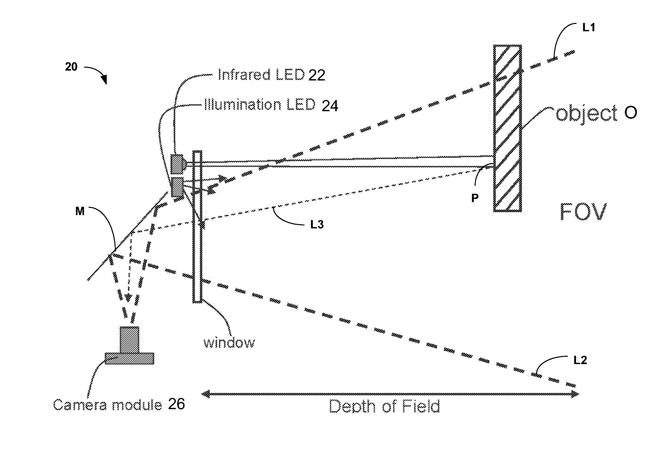
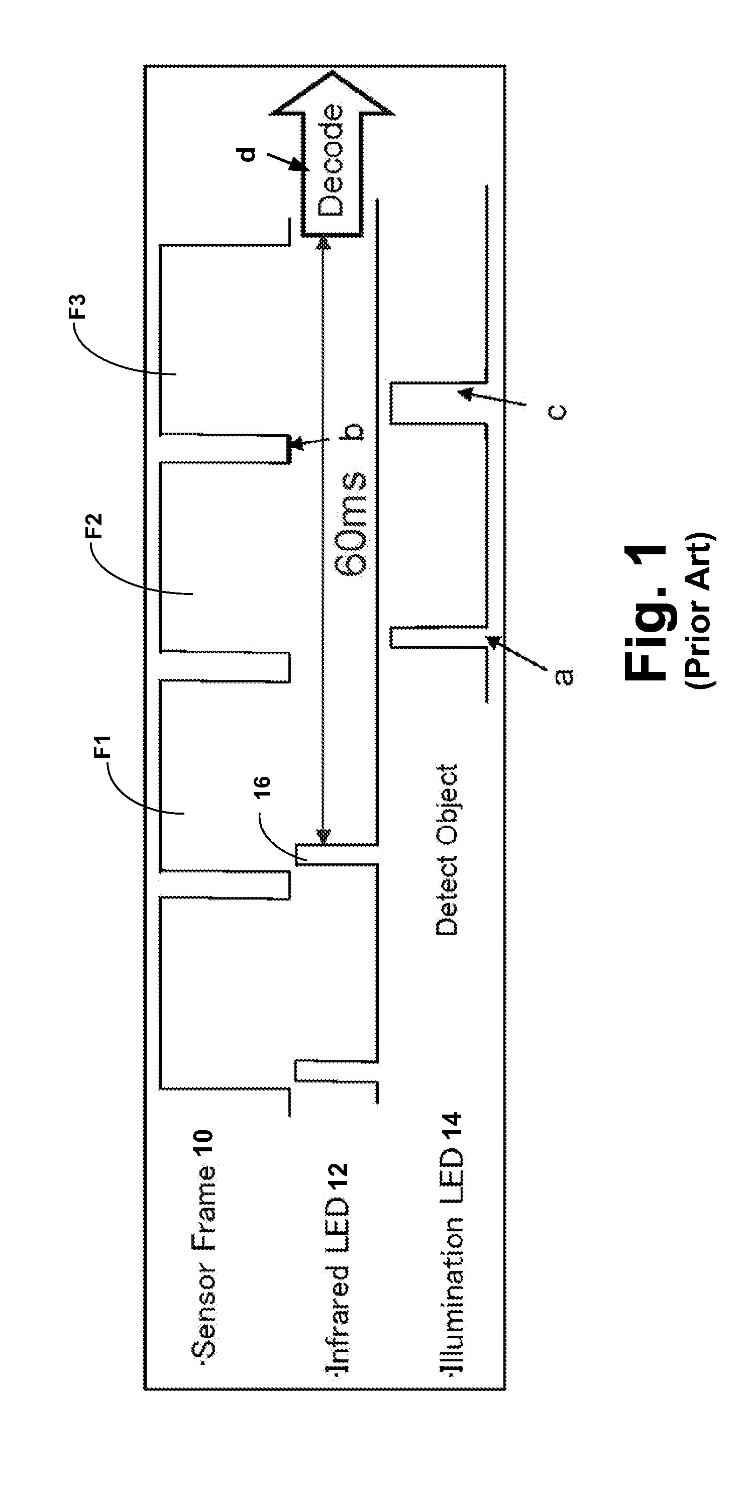
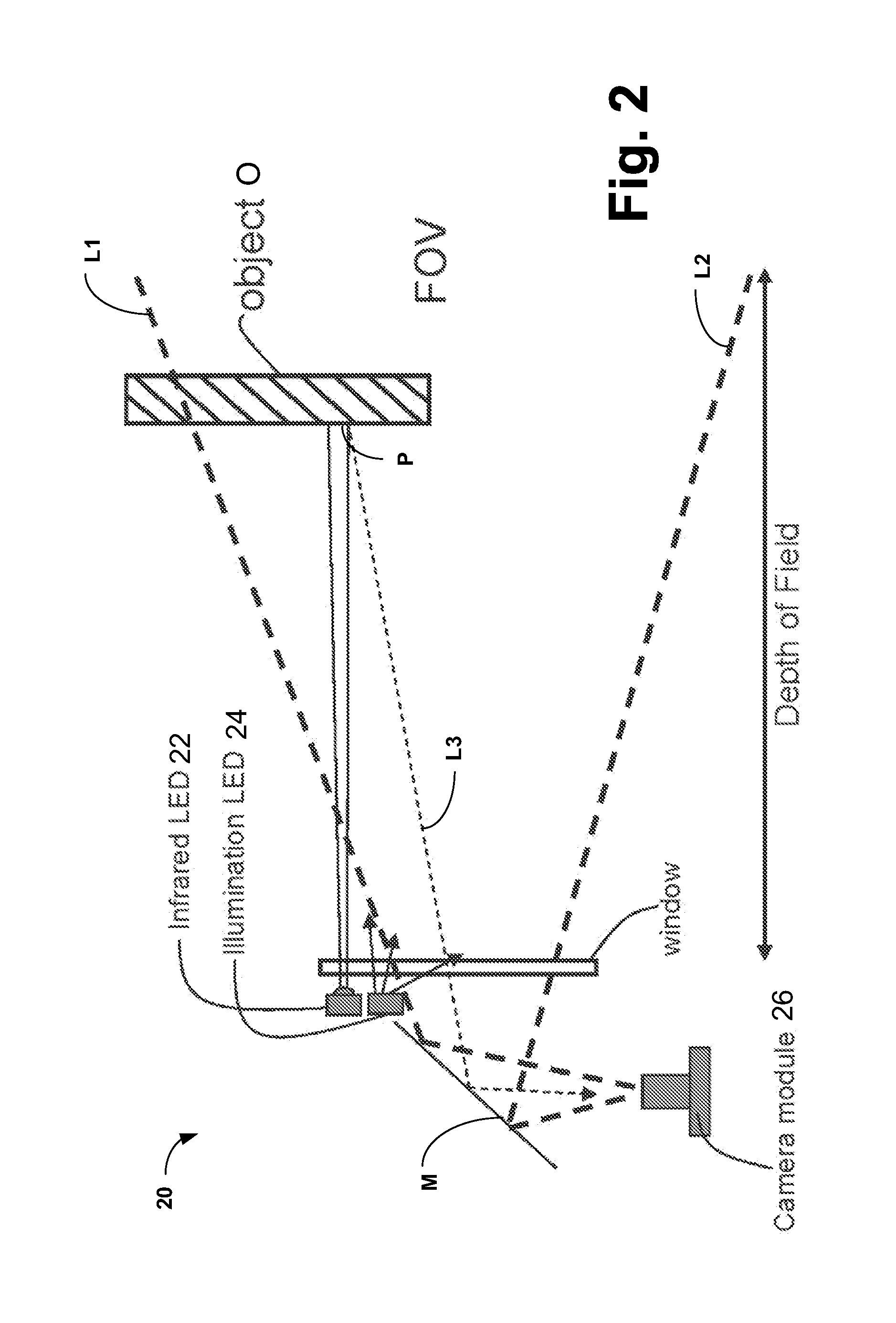
[0018]Turning now to the drawings, FIG. 2 is a schematic representation of an optical imaging device system 20 embodying the present invention. FIG. 3 is a timing chart useful in describing the operation of system 20 of FIG. 2, and FIG. 4 is a flow chart, also useful in describing the operation.

[0019]As may be seen in FIG. 2, system 20 includes an infrared light emitting diode (LED 22), which emits infrared radiation and an illumination LED 24, which emits visible light. Radiation from LEDs 22 and 24 is directed at a face of an object O, which bears an optical code, preferably in an area above a point P where the infrared radiation impinges. A camera module 26 having a field of view FOV defined by the lines L1, L2 monitors object O through a mirror M. Line L3 represents an image of point P reflected from object O to camera module 26.

[0020]In operation, as represented by block 100 in the flow chart of FIG. 4, the infrared LED 22 is pulsed during a sensor frame F2 and, when the image ...


PUM


Abstract

In an optical code detection system and method, infrared pulses are utilized to detect the presence of an object within the range of an optical imaging device, but the image of an infrared pulse reflected from the object is also analyzed to determine the distance between the object and the imaging device. An illumination pulse is then produced to illuminate the optical code on the object, and the characteristic of that pulse, such as duration, are controlled to provide appropriate exposure for an object at the detected distance.

Description

BACKGROUND OF THE INVENTION[0001]The present invention relates generally to optical code detection and reading systems and, more particularly, concerns an optical code reading system and method which provide adaptive exposure control.[0002]Anyone who has shopped in a modern supermarket is familiar with optical code imaging devices, which facilitate rapid checkout by scanning bar codes imprinted on product packages. This is a relatively undemanding application of bar code reading, as a package is essentially brought to a standstill by the operator for purposes of scanning the bar code.[0003]More recently, optical code readers have been utilized in production lines where items are assembled, where they are inspected, where they are packaged, and the like. This application of optical code reading is far more demanding, as products move down a production line at a relatively high speed, for example, on a conveyor belt. In order to avoid the creation of a bottle neck on the production li...

Claims


Application Information

Patent Timeline
Patent Type & Authority Applications(United States)
IPC IPC(8): G06K7/12G06K7/10
CPCG06K7/10801G06K7/10732
Inventor FUKUBA, KENKOMI, SATOSHISAMPEI, TAKASHIYAMAZAKI, TOKUMA
Owner OPTICON
Why Eureka
Try Eureka