Vehicle driving apparatus

Inactive Publication Date: 2011-09-01
AISIN AW CO LTD
View PDF4 Cites 18 Cited by
  • Summary
  • Abstract
  • Description
  • Claims
  • Application Information

AI Technical Summary

Benefits of technology

[0010]According to the first aspect, an alignment operation for aligning the rotary axis center position of at least a part of the plurality of transmission rotary elements can be performed before engaging the frictional engagement element and shifting to the transmission state by causing the drive power source to generate driving force in order to rotate the drive input member and rotating the shift input member via the fluid coupling. Therefore, the frictional engagement element can be engaged in a state where the rotary axis centers of the transmission rotary elements are aligned. As a result, problems arising when the frictional engagement element is engaged while the rotary axis centers of the transmission rotary elements are eccentric can be suppressed. Here, a condition for performing the shift input rotation operation is that the state shift command for shifting the transmission apparatus from the non-transmission state to the transmission state is input in a state where the drive power source does not generate the driving force, and therefore alignment can be performed appropriately in a situation where the rotary axis centers of the transmission rotary elements may be eccentric.
[0011]Further, according to the first aspect, rotation of the drive input member generated by the driving force of the drive power source is transmitted to the shift input member via the fluid coupling during the shift input rotation opera

Problems solved by technology

When this control is performed, however, it is difficult to control the engagement pressure of the brake with a high degree of precision, and it is therefore difficult to suppress torque transmission to the vehicle wheel side.
With this constitution, however, processing is required to perform an e

Method used


Image

  • Vehicle driving apparatus
  • Vehicle driving apparatus
  • Vehicle driving apparatus

Examples


first embodiment

1. First Embodiment

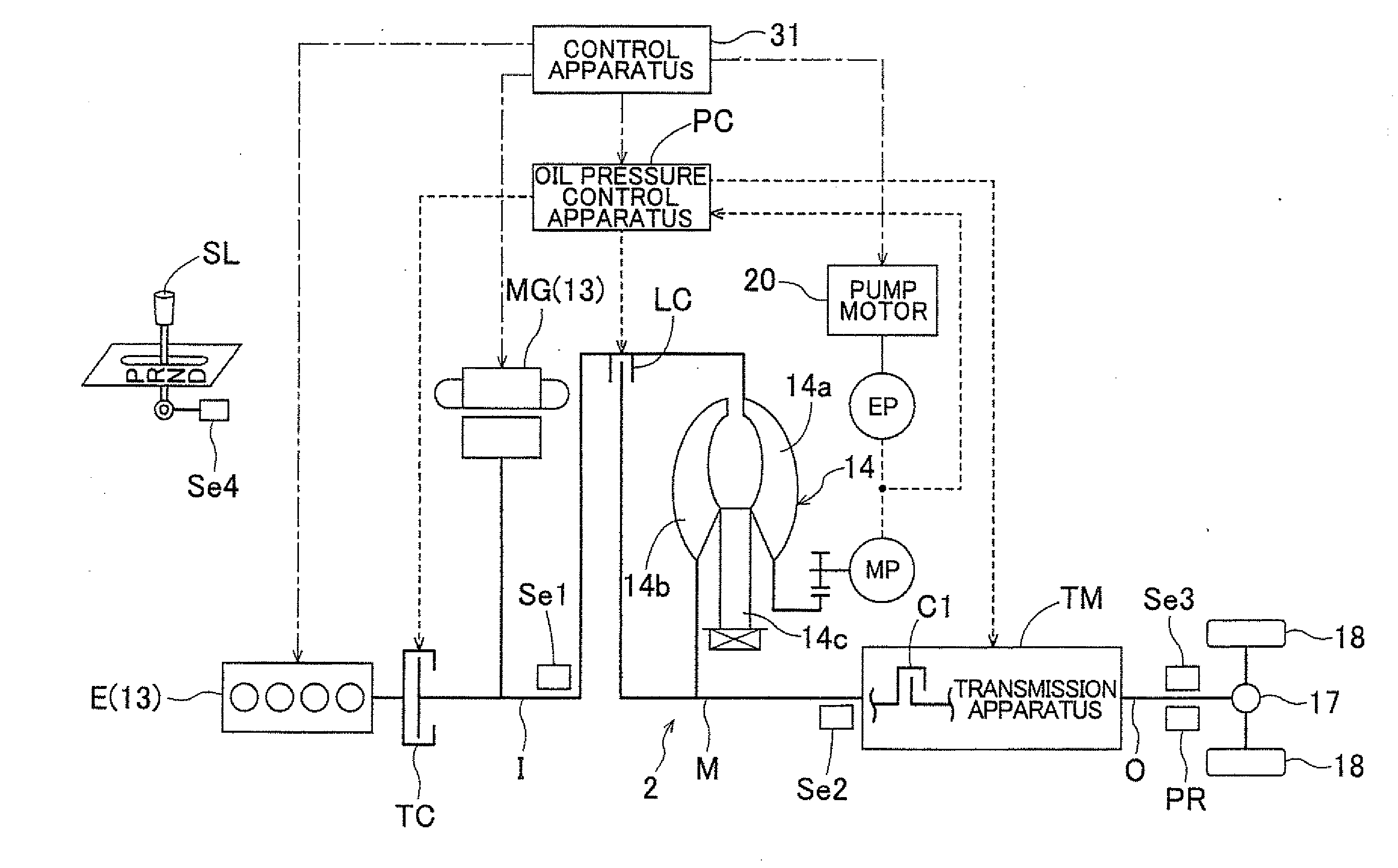
[0030]A first embodiment of the present invention will now be described on the basis of the drawings. In this embodiment, a case in which a control apparatus 31 according to the present invention is applied to a vehicle driving apparatus 2 for a hybrid vehicle will be described as an example. FIG. 1 is a pattern diagram showing an outline of the constitution of the vehicle driving apparatus 2 according to this embodiment. Note that in FIG. 1, solid lines indicate driving force (torque) transmission paths, dotted lines indicate supply paths for a working oil command pressure or a working oil, and dot-dash lines indicate electric signal transmission paths. As shown in the drawing, the vehicle driving apparatus 2 according to this embodiment basically includes an engine E and a rotating electrical machine MG serving as drive power sources 13, a torque converter 14 serving as a fluid coupling, a transmission apparatus TM, and the control apparatus 31 for controlling a...

second embodiment

4. Second Embodiment

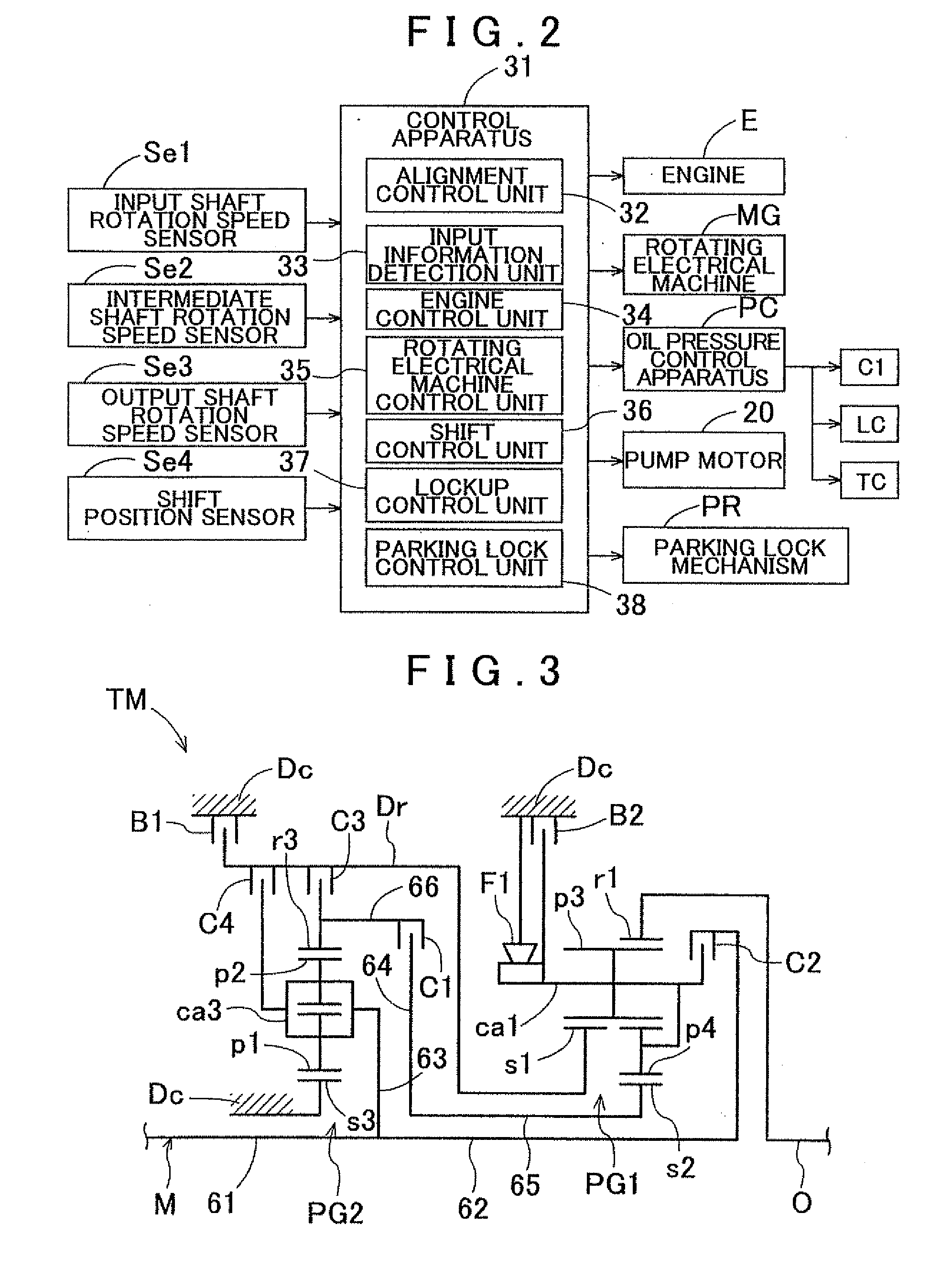
[0092]Next, a second embodiment of the present invention will be described. In the first embodiment described above, the alignment control unit 32 determines whether or not alignment is complete (whether or not to start engagement) on the basis of the elapsed time (the timer time) following the start of the alignment control, but in this embodiment, the alignment control unit 32 determines whether or not alignment is complete on the basis of the rotation speed of the intermediate shaft M. Further, in the first embodiment, the alignment control unit 32 determines whether or not to stop generation of the driving force by the drive power source 13 and start full engagement control on the basis of the increase in the rotation speed difference between the input shaft I and the intermediate shaft M, but in this embodiment, the alignment control unit 32 determines whether or not to stop generation of the driving force by the drive power source 13 using a point in time a...


PUM


Abstract

A vehicle driving apparatus configured with a drive power source, a fluid coupling, a transmission apparatus; and a control apparatus. A rotation of a drive input member driven by the drive power source is transmitted to a shift input member via the fluid coupling and a rotation of the shift input member is shifted by the transmission apparatus and then transmitted to an output member. When a state shift command for shifting from a non-transmission state to a transmission state is input into a control apparatus in a state in which the drive power source does not generate a driving force, the control apparatus performs a shift input rotation operation before engaging a frictional engagement element and shifting to the transmission state by causing the drive power source to generate the driving force and rotating the shift input member via the fluid coupling while maintaining the non-transmission state.

Description

INCORPORATION BY REFERENCE[0001]The disclosure of Japanese Patent Application No. 2010-042891 filed on Feb. 26, 2010 including the specification, drawings and abstract is incorporated herein by reference in its entirety.BACKGROUND OF THE INVENTION[0002]The present invention relates to a vehicle driving apparatus that includes a drive power source, a fluid coupling, a transmission apparatus, and a control apparatus for controlling at least the drive power source and the transmission apparatus, in which a rotation of a drive input member driven by the drive power source is transmitted to a shift input member via the fluid coupling and a rotation of the shift input member is shifted by the transmission apparatus and then transmitted to an output member.DESCRIPTION OF THE RELATED ART[0003]In recent years, hybrid vehicles that use both an internal combustion engine and a rotating electrical machine as drive power sources have become popular. In this type of hybrid vehicle, internal combu...

Claims


Application Information

Patent Timeline
IPC IPC(8): B60W10/02B60W10/06B60W10/08B60W10/10B60K6/36B60K6/48B60K6/547B60L50/16B60T1/06B60W20/00F16H61/02F16H63/34F16H63/50
CPCB60W10/115B60W10/02B60W20/00B60L2240/486B60W2510/1015Y10T477/26B60W10/08F16H2312/14F16H61/0204B60W10/06Y02T10/6286Y10T477/638Y02T10/62B60W10/026F16H61/02B60W10/10
Inventor TSUTSUI, HIROSHIUOZUMI, SHINGOTORII, TAKESHIMURAKAMI, SHIN-ICHIROUMIYAZAWA, TAKAHIRO
Owner AISIN AW CO LTD
Why Eureka
Try Eureka