Fuel injection controller for internal combustion engine

a fuel injection controller and internal combustion engine technology, applied in the direction of electrical control, process and machine control, etc., can solve the problems of deteriorating air-fuel ratio estimation accuracy, affecting the accuracy of air-fuel ratio detection, and affecting the accuracy of air-fuel ratio estimation with respect to each cylinder. , to achieve the effect of high accuracy, low engine load condition, and high accuracy

Inactive Publication Date: 2011-09-01
DENSO CORP
View PDF6 Cites 12 Cited by
  • Summary
  • Abstract
  • Description
  • Claims
  • Application Information

AI Technical Summary

Benefits of technology

[0014]The required fuel injection quantity (required fuel injection pulse width) per a single injection in the split fuel injection becomes almost the same as the required fuel injection quantity (required fuel injection pulse width) in low engine-load condition. The injection-quantity variation of each cylinder in performing the split fuel injection becomes almost the same as the injection-quantity variation in low engine-load condition. During the split fuel injection, the air-fuel ratio deviates by a specified amount which corresponds to the injection-quantity variation when the engine is driven in low engine-load condition. Further, when the engine is driven in high engine-load condition and the split fuel injection is performed, the exhaust gas quantity is relatively large, so that the air-fuel ratio detection accuracy of the air-fuel ratio sensor becomes high.
[0015]Therefore, based on the variation in the air-fuel ratio detected by the air-fuel ratio sensor during the split fuel injection, the injection-quantity variation in low engine-load condition can be learned with high accuracy.
[0016]Further, since the number of times of fuel injection in the split fuel injection is determined based on the fuel injection quantity in the fuel injection quantity range where the learning is executed, the number of times can be properly determined and the fuel injection quantity per one fuel injection can be surely established within the present fuel injection quantity range. Thus, the injection-quantity variation can be correctly learned.

Problems solved by technology

That is, it is likely that linearity in variation characteristics of actual fuel injection quantity (actual fuel injection period) is deteriorated with respect to required fuel injection quantity (required fuel injection pulse) when the required fuel injection quantity is relatively small.
However, when the engine is driven in low engine-load condition, the exhaust gas quantity is decreased and the estimation accuracy of the air-fuel ratio with respect to each cylinder is deteriorated.
Thus, the variation in air-fuel ratio between cylinders is hardly obtained with high accuracy.
The injection-quantity variation in each cylinder can not be corrected accurately.
That is, it is likely that linearity in variation characteristics of actual fuel injection quantity is deteriorated with respect to a fuel injection pulse width (fuel injection period) when the fuel injection quantity is relatively small.
However, when the engine is driven in low engine-bad condition, the exhaust gas quantity is decreased and the estimation accuracy of the air-fuel ratio with respect to each cylinder is deteriorated.
Thus, the variation in air-fuel ratio between cylinders is hardly obtained with high accuracy.
The injection-quantity variation in each cylinder can not be corrected accurately.

Method used


Image

  • Fuel injection controller for internal combustion engine
  • Fuel injection controller for internal combustion engine
  • Fuel injection controller for internal combustion engine

Examples


first embodiment

[0031]Referring to FIGS. 1 to 4, a first embodiment will be described hereinafter.

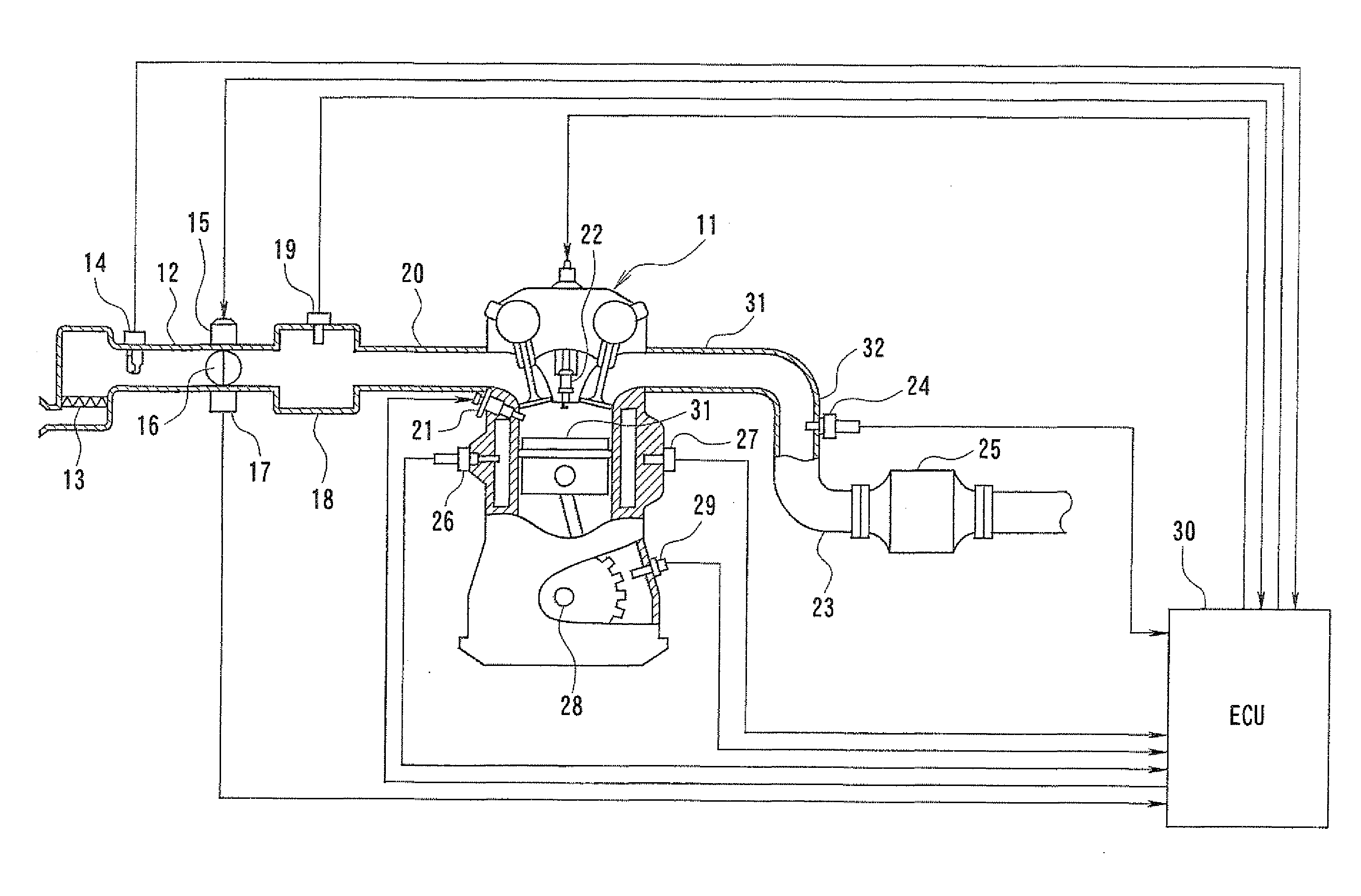
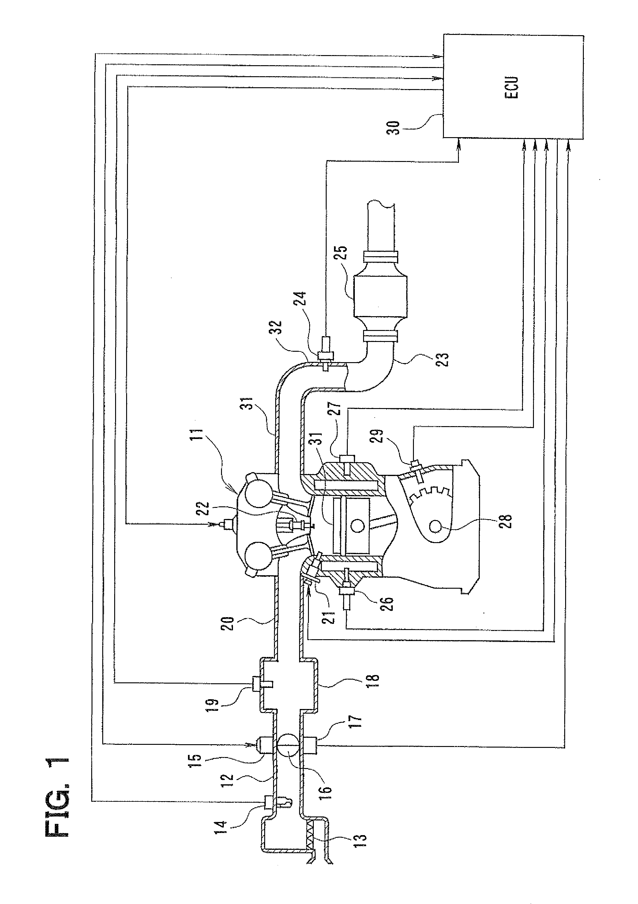
[0032]FIG. 1 shows an engine control system. An air cleaner 13 is arranged upstream of an intake pipe 12 of an internal combustion engine 11 which is a direct injection engine. An airflow meter 14 detecting an intake air flow rate is provided downstream of the air cleaner 13. A throttle valve 16 driven by a DC-motor 15 and a throttle position sensor 17 detecting a throttle position (throttle opening degree) are provided downstream of the air flow meter 14.

[0033]A surge tank 18 including an intake air pressure sensor 19 is provided downstream of the throttle valve 16. The intake air pressure sensor 19 detects intake air pressure. An intake manifold 20 is connected to the surge tank 18. A fuel injector 21 is mounted on each cylinder at a vicinity of an intake air port in order to inject fuel into the cylinder directly. A spark plug 22 is mounted on a cylinder head of the engine 11 corresponding to each c...

third embodiment

[0076]Referring to FIGS. 7 to 10, a third embodiment will be described hereinafter.

[0077]FIG. 7 shows an engine control system according to the third embodiment. An air cleaner 113 is arranged upstream of an intake pipe 112 of an internal combustion engine 111 which is a direct injection engine. An airflow meter 114 detecting an intake air flow rate is provided downstream of the air cleaner 113. A compressor 128 of a turbocharger 126 and an intercooler 132 are provided downstream of the airflow meter 114. A boost pressure sensor 133 is provided downstream of the interceder 132 in order to detect boost pressure upstream of a throttle valve 116. The throttle valve 116 driven by a DC-motor 115 and a throttle position sensor 117 detecting a throttle position (throttle opening degree) are provided downstream of the boost pressure sensor 133.

[0078]A surge tank 118 including an intake air pressure sensor 119 is provided downstream of the throttle valve 116. The intake air pressure sensor 1...

fourth embodiment

[0102]Referring to FIG. 11, a fourth embodiment will be described hereinafter. In the fourth embodiment, the same parts and components as those in the third embodiment are indicated with the same reference numerals and the same descriptions will not be reiterated.

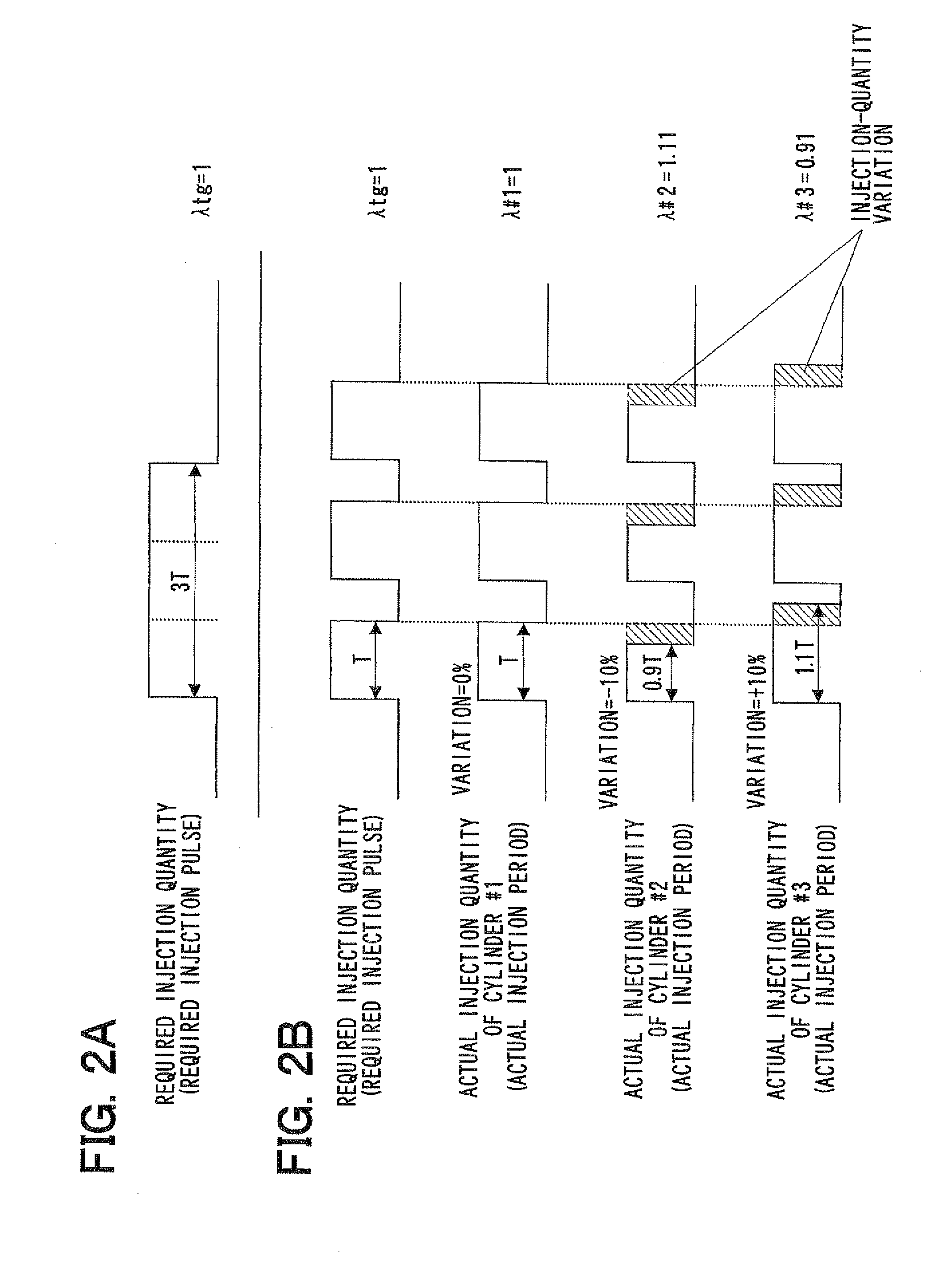
[0103]According to the present embodiment, the ECU 142 executes an injection-quantity variation learning routine shown in FIG. 11. The number N of split fuel injection is sequentially changed to learn the injection-quantity variation of the fuel injector 121, so that the injection-quantity variation is learned in multiple fuel injection quantity ranges.

[0104]In step 1201, the computer determines whether the engine driving condition (engine speed, engine load and the like) is stable. When the answer is YES in step 1201, the procedure proceeds to step 1202 in which the computer determines whether the engine is driven in high engine-load condition. When the answer is YES in step 1202, the procedure proceeds to step 1203 in whi...


PUM


Abstract

When an engine is driven in a high engine-load condition, a split fuel injection is performed in which a required fuel injection quantity is injected by multiple fuel injections. While the split fuel injection is performed, an actual air-fuel ratio of each cylinder is individually computed based on the output of the air-fuel ratio sensor. Based on the actual air-fuel ratio and a reference air-fuel ratio, an injection-quantity variation of each cylinder is computed. A correction value is computed and learned in order to correct the injection-quantity variation of each cylinder.

Description

CROSS-REFERENCE TO RELATED APPLICATION[0001]This application is based on Japanese Patent Applications No. 2010-42030 filed on Feb. 26, 2010, and No. 2010-80305 filed on Mar. 31, 2010, the disclosures of which are incorporated herein by reference.FIELD OF THE INVENTION[0002]The present invention relates to a fuel injection controller for an internal combustion engine. The fuel injection controller is provided with a function that computes variation information about fuel injection quantity injected through a fuel injector when the engine is driven in low engine-load condition. Also, the fuel injection controller is provided with a function that computes an injection-quantity variation of a fuel injector when the engine is driven in low engine-load condition.BACKGROUND OF THE INVENTION[0003]JP-2004-183616A (US-2004-0158387A1) shows a fuel injection control system in which air-fuel ratio in each cylinder is estimated by means of a module correlating air-fuel ratio in each cylinder with...

Claims


Application Information

Patent Timeline
Patent Type & Authority Applications(United States)
IPC IPC(8): F02D41/30
CPCF02D41/1456F02D41/2441Y02T10/44F02D41/402F02D41/2467Y02T10/40
Inventor MITSUDA, TETSUJIUEDA, KUNIAKI
Owner DENSO CORP
Why Eureka
Try Eureka