Dye-sensitized solar cell

Inactive Publication Date: 2011-09-08
CASIO COMPUTER CO LTD
View PDF6 Cites 5 Cited by
  • Summary
  • Abstract
  • Description
  • Claims
  • Application Information

AI Technical Summary

Benefits of technology

[0009]The present invention is directed to providing a dye-sensitized solar cell with high generating efficiency.

Problems solved by technology

Although a solar cell using silicon crystal has already been put into practical use, manufacturing the cell involves high energy costs.
Therefore, a potential difference occurs between the titanium oxide and the electrolyte.
Thus, in the dye-sensitized solar cell, a thick film is formed of very small grains, and therefore, coupling between the grains made of titanium oxide is easily deteriorated.
As a result, there is a problem that generating efficiency of the solar cell deteriorates.

Method used


Image

  • Dye-sensitized solar cell
  • Dye-sensitized solar cell
  • Dye-sensitized solar cell

Examples


first embodiment

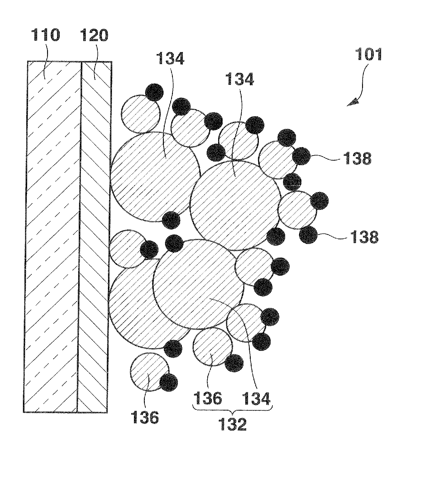
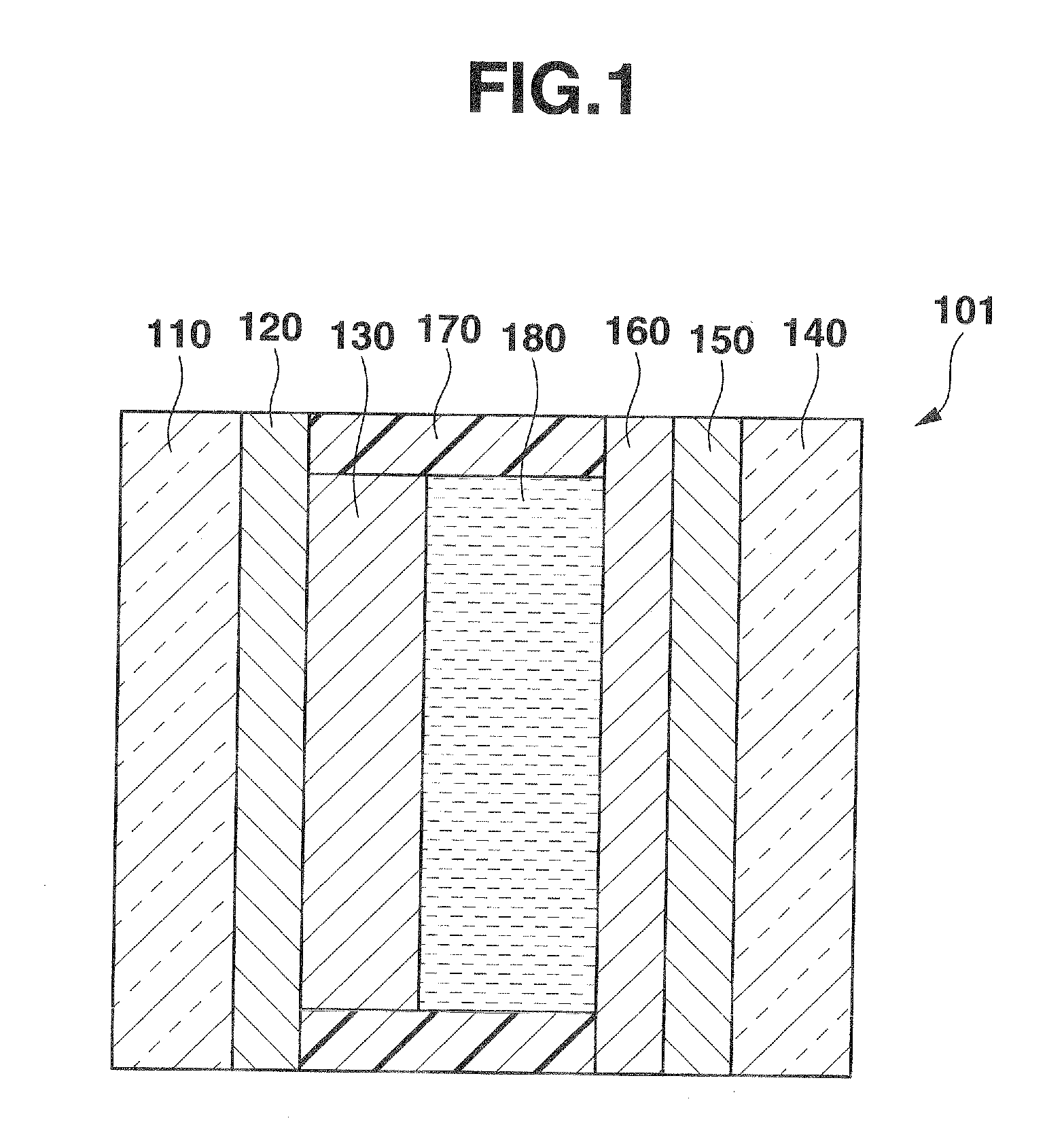
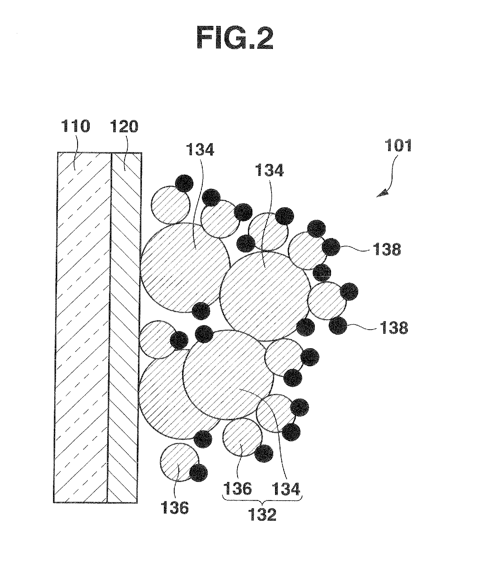
[0026]A first embodiment of the present invention will now be described with reference to the drawings. In a dye-sensitized solar cell 101 according to the first embodiment, a transparent conductive film 120 as a first electrode made of indium tin oxide (ITO) or fluorine-doped tin oxide (FTO) is formed on a transparent first substrate 110 made of, for example, glass or a film, as shown in FIG. 1. The transparent conductive film 120 may be patterned. A current collector pattern made of silver may be provided as a layer above or below the transparent conductive film 120. An electron-collector / dye layer 130 is formed on the transparent conductive film 120. The electron-collector / dye layer 130 will be described in details later.

[0027]A conductive film 150 as a second electrode is formed on a transparent second substrate 140 which is made of, for example, glass or a film and opposed to the first substrate 110. A catalyst layer 160 made of platinum or carbon is formed on the conductive fi...

second embodiment

[0047]A second embodiment of the present invention will now be described below with reference to the drawings. In a dye-sensitized solar cell 201 according to the second embodiment, a transparent conductive film 220 as a first electrode made of indium tin oxide (ITO) or fluorine-doped tin oxide (FTO) is formed on a surface (a first surface) of a transparent first substrate 210 made of, for example, glass or a film, as shown in FIG. 5. The transparent conductive film 220 may be patterned. A current collector pattern made of silver may also be provided as a layer above or below the transparent conductive film 220. An electron-collector / dye layer 230 is formed on the transparent conductive film 220. The electron-collector / dye layer 230 will be described in details later.

[0048]The electron-collector / dye layer 230 comprises an electron collector including grains of, for example, anatase titanium oxide, and dye made of, for example, ruthenium dye (e.g., N719 dye). The electron collector h...

example

[0056]An example of the dye-sensitized solar cell 201 according to the second embodiment will now be described. In a dye-sensitized solar cell 201 according to the present embodiment, fine roughness was formed on a second substrate 240, and a surface of a catalyst layer 260 was formed as a diffusion / reflection surface. The dye-sensitized solar cell 201 of the present embodiment was compared with a dye-sensitized solar cell 290 as a comparative example in which a second substrate 240 was formed to be a flat surface and a surface of a catalyst layer 260 was formed to be a mirror surface. An index used for comparison was conversion efficiency η as a ratio of energy of generated electricity to energy of incident light.

[0057]In the dye-sensitized solar cell 201 according to the present embodiment, roughness was formed on the second substrate 240 by chemical polishing. A surface shape of the second substrate 240 which was formed to be rough is shown in FIGS. 6A and 6B. FIG. 6A is a plan v...


PUM


Abstract

A dye-sensitized solar cell includes a first electrode, a second electrode, an electron-collector / dye layer, and an electron donor. The second electrode faces the first electrode. The electron-collector / dye layer provided on the first electrode includes an electron collector and dye. The electron collector includes first electron collector grains and second electron collector grains. The first electron collector grains have a diameter or diameters within a first diameter range and the second electron collector grains have a diameter or diameters within a second diameter range. A minimum value of the second diameter range is greater than a maximum value of the first diameter range. The electron donor is provided between the electron-collector / dye layer and the second electrode.

Description

CROSS-REFERENCE TO RELATED APPLICATIONS[0001]This application is based upon and claims the benefit of priority from prior Japanese Patent Applications No. 2010-048286, filed Mar. 4, 2010; and No. 2010-070574, filed Mar. 25, 2010, the entire contents of both of which are incorporated herein by reference.BACKGROUND OF THE INVENTION[0002]1. Field of the Invention[0003]The present invention relates to a dye-sensitized solar cell[0004]2. Description of the Related Art[0005]Recent attention has focused on solar cells which utilize clean, inexpensive natural energy without damaging the environment. Although a solar cell using silicon crystal has already been put into practical use, manufacturing the cell involves high energy costs. In contrast a dye-sensitized solar cell, for example, as disclosed in Jpn. Pat. Appln. KOKAI 2008-41258, can be manufactured with a large-area element at lower cost than a solar cell using silicon crystal, and further is capable of achieving a flexible cell.[000...

Claims


Application Information

Patent Timeline
IPC IPC(8): H01L31/0224H01L31/0236
CPCH01G9/20Y02E10/542H01G9/2031
Inventor KOBAYASHI, KUNPEIBABA, MIKIOARAI, NORIHIRO
Owner CASIO COMPUTER CO LTD
Why Eureka
Try Eureka