Handheld power tool having a switchable gear

Active Publication Date: 2011-09-08
ROBERT BOSCH GMBH
View PDF3 Cites 10 Cited by
  • Summary
  • Abstract
  • Description
  • Claims
  • Application Information

AI Technical Summary

Benefits of technology

[0004]An object of the exemplary embodiments and / or exemplary methods of the present invention is to provide a handheld power took having a multistage gear which is switchable between at least two gear stages, using simple structural means, in such a way that it is possible to reliably change between the gear stages under different operating conditions, in particular under load, and at reduced component stress.
[0007]In the exemplary embodiment according to the present invention, the latching member is mounted in the housing within a limited angle segment between two end stop positions in such a way that it is able to rotate around the rotation axis of the tool. In contrast to embodiments according to the related art, the non-rotational connection of the latching member to the housing is canceled at least to the extent that a rotation of the latching member between the two end stop positions is enabled, so that the latching member may change its angular position between these two end stop positions. In an exemplary embodiment, each of these end stop positions is assigned to a latched position or to an unlatched position and thus also to a particular gear stage. To change the gear stage, the latching member executes a limited angular rotation, so that, for example when moving from the unlatched position to the latched position, the latching member undergoes a rotational acceleration and thus a continuous change in rotational angular velocity until it reaches the diametrically opposed end stop position and, in contrast to the related art, no abrupt coupling, accompanied by a jerk, of the gear component occurs between standstill and rotation. This advantage takes effect when the latching member moves from the latched position to the unlatched position as well as in the opposite direction, i.e., both when changing from the first gear stage to the second gear stage and from the second gear stage to the first gear stage. Furthermore, a gear change is made possible, in particular when the handheld power tool is under load, without this resulting in an impermissibly high stress on the component.

Problems solved by technology

The switching operation may not be reliably carried out under load; in this case, the operator must turn the handheld power tool off and then on again, the switching operation not being completed until a restart.

Method used


Image

  • Handheld power tool having a switchable gear
  • Handheld power tool having a switchable gear
  • Handheld power tool having a switchable gear

Examples


Embodiment Construction

[0017]In the figures, identical components are provided with identical reference numerals.

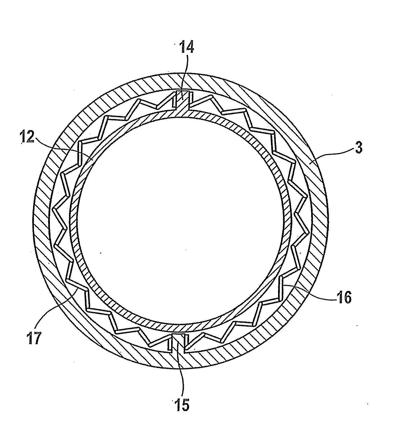
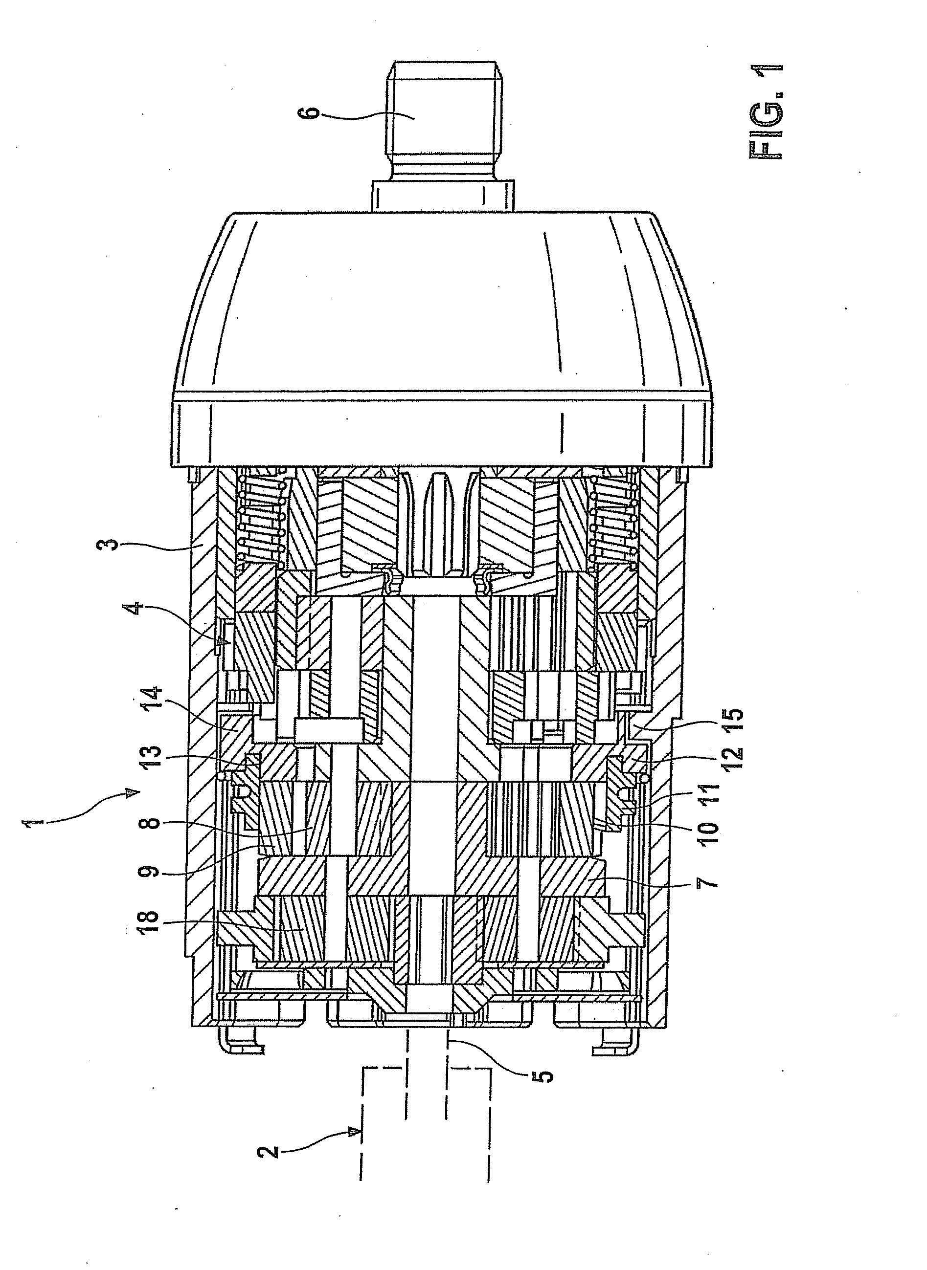
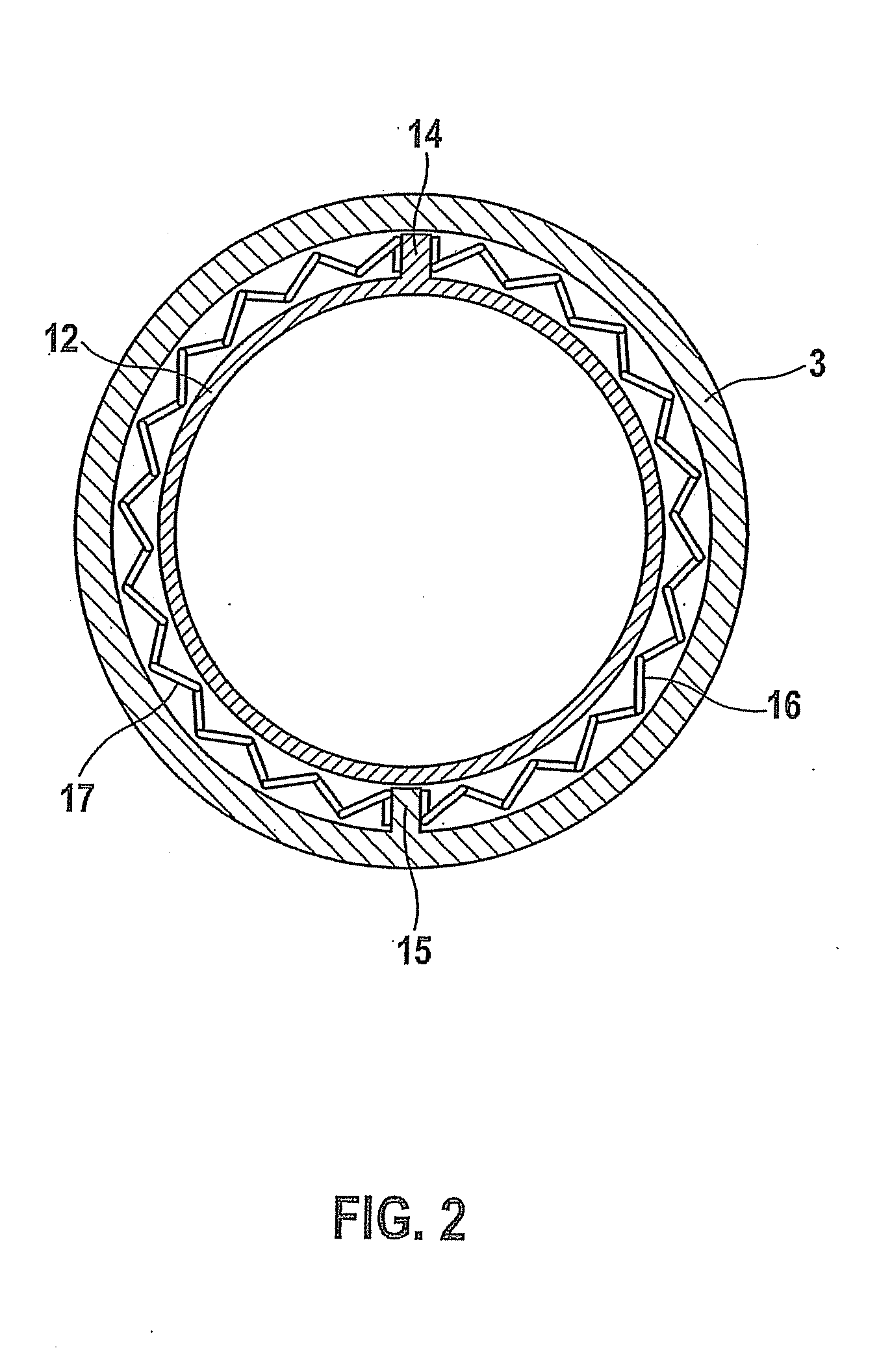
[0018]The handheld power tool 1 illustrated in FIG. 1 is, for example, a cordless screwdriver or a cordless drill. Handheld power tool 1 includes an electric drive motor 2, which is illustrated only as an outline, in a housing 3, motor shaft 5 of drive motor 2 driving a planet gear 4 in housing 3, planet gear 4 being rotationally coupled with a tool receptacle part 6. Planet gear 4 has a three-stage design and includes two gear stages, it being possible to switch back and forth between the gear stages to change the step-down and torque ratios.

[0019]Planet gear 4 includes a sun wheel (stage 1) 7, which carries planet wheels 18. An annulus gear wheel (stage 2) 9, which surrounds planet wheels 8 and is rotationally coupled with an annulus wheel 11 via an engaging gearing 10, is assigned to planet gear 4, annulus wheel 11 being able to execute an axial adjusting movement relative to housing 3. Annu...


PUM


Abstract

A handheld power tool has a switchable gear having at least two gear stages which are engaged via an adjustable switching member, the switching member being held in a latching position with a latching member in a first gear stage and in an unlatched position in a second gear stage. The latching member is rotatably mounted in the housing within a limited angular section between two end stop positions.

Description

FIELD OF THE INVENTION[0001]The present invention relates to a handheld power tool having a switchable gear.BACKGROUND INFORMATION[0002]A handheld power tool designed as a cordless screwdriver, which is equipped with an electric drive motor which drives a rotatably mounted tool receptacle for receiving a tool via a multistage planet gear, is discussed in DE 10 2004 058 809 A1.[0003]Planet gears of this type may usually be switched between two gear stages having a slow rotational speed and high torque or having a higher rotational speed and lower torque. A slide switch manually adjusts an annulus wheel in the axial direction between a latched position having a latching disk fixed in a housing and an unlatched position, the annulus gear wheel being rotationally connected to a sun wheel of the planet gear in such a way that the annulus gear wheel is also fixedly coupled with the housing in the latched position and the annulus gear wheel may rotate in the unlatched position. When adjust...

Claims


Application Information

Patent Timeline
IPC IPC(8): B25F5/00
CPCB25B21/00F16H3/62F16H59/041B25F5/001
Inventor ROEHM, HEIKO
Owner ROBERT BOSCH GMBH
Why Eureka
Try Eureka