
Pressure sensor and process of manufacturing same

Active Publication Date: 2017-02-02
KISTLER HLDG AG
View PDF6 Cites 2 Cited by
  • Summary
  • Abstract
  • Description
  • Claims
  • Application Information

AI Technical Summary

Benefits of technology

The invention is a pressure sensor that reduces mechanical stress on the components involved in signal transmission. It includes an electrode arrangement and an evaluation unit with a reinforcement element that dampens mechanical resonance vibrations of the electric circuit board that occur during use. The reinforcement element fixes the electric circuit board relative to the evaluation unit housing so as to restrain the electric circuit board's freedom of movement in the radial plane. This ensures that engine vibrations only induce dampened mechanical resonance vibrations in the radial plane, thereby permanently reducing the mechanical stress on the components involved in signal transmission.

Problems solved by technology

Furthermore, the reinforcement element is arranged in a radial plane between the electric circuit board and the evaluation unit housing and dampens mechanical resonance vibrations of the electric circuit board that occur in the radial plane.
Thus, engine vibrations are only able to induce in the electric circuit board, dampened mechanical resonance vibrations in the radial plane.

Method used


Image

  • Pressure sensor and process of manufacturing same
  • Pressure sensor and process of manufacturing same
  • Pressure sensor and process of manufacturing same

Examples


Embodiment Construction

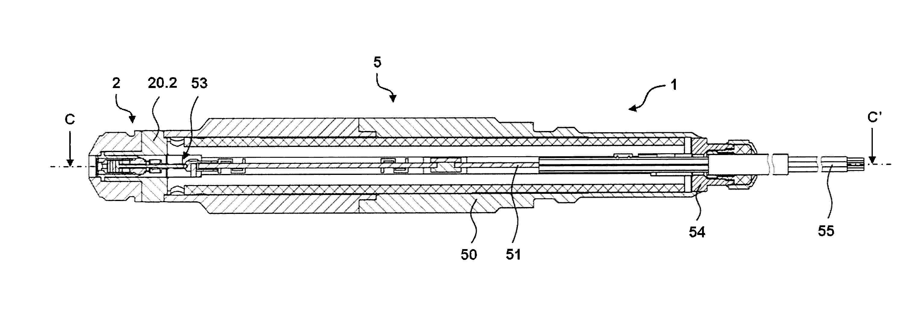
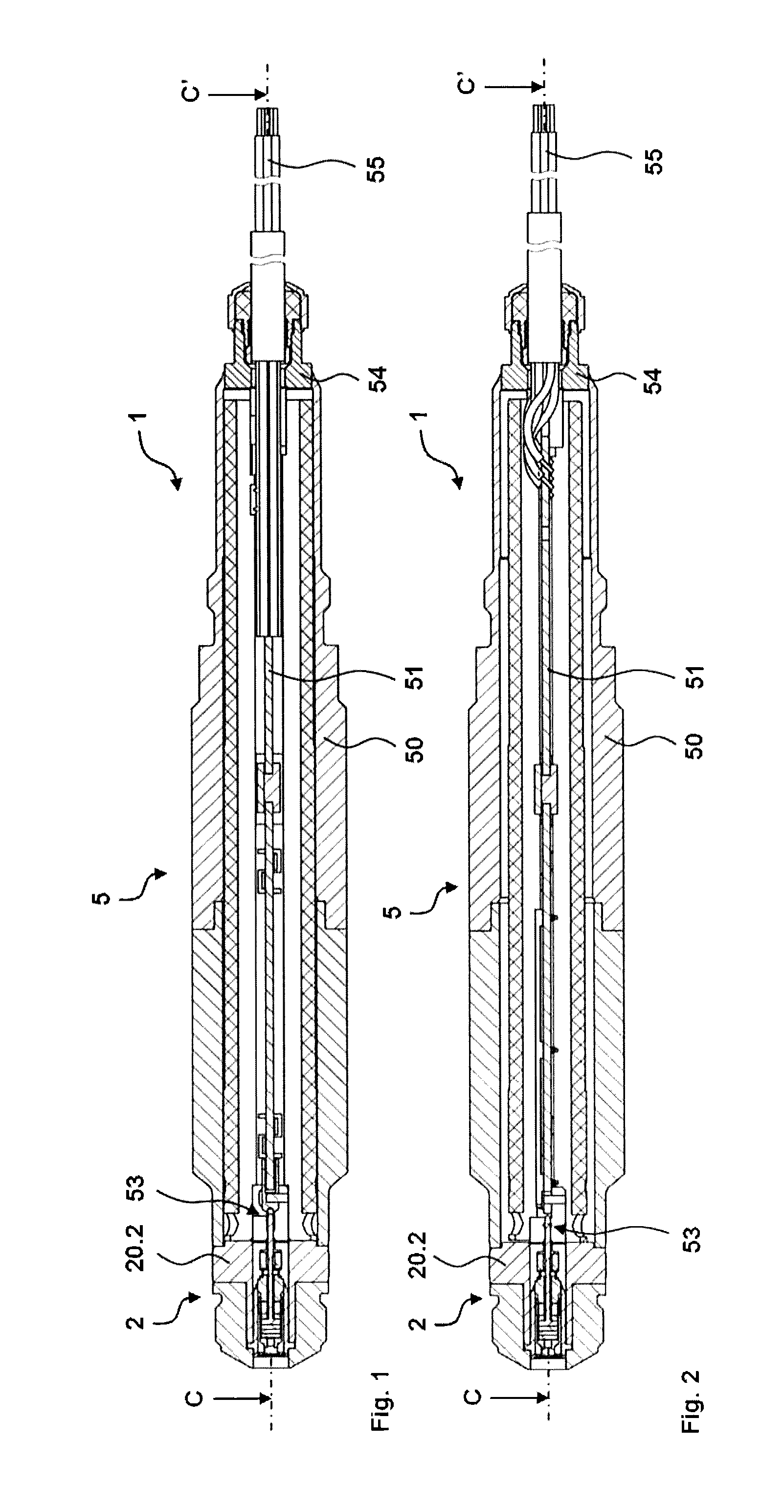
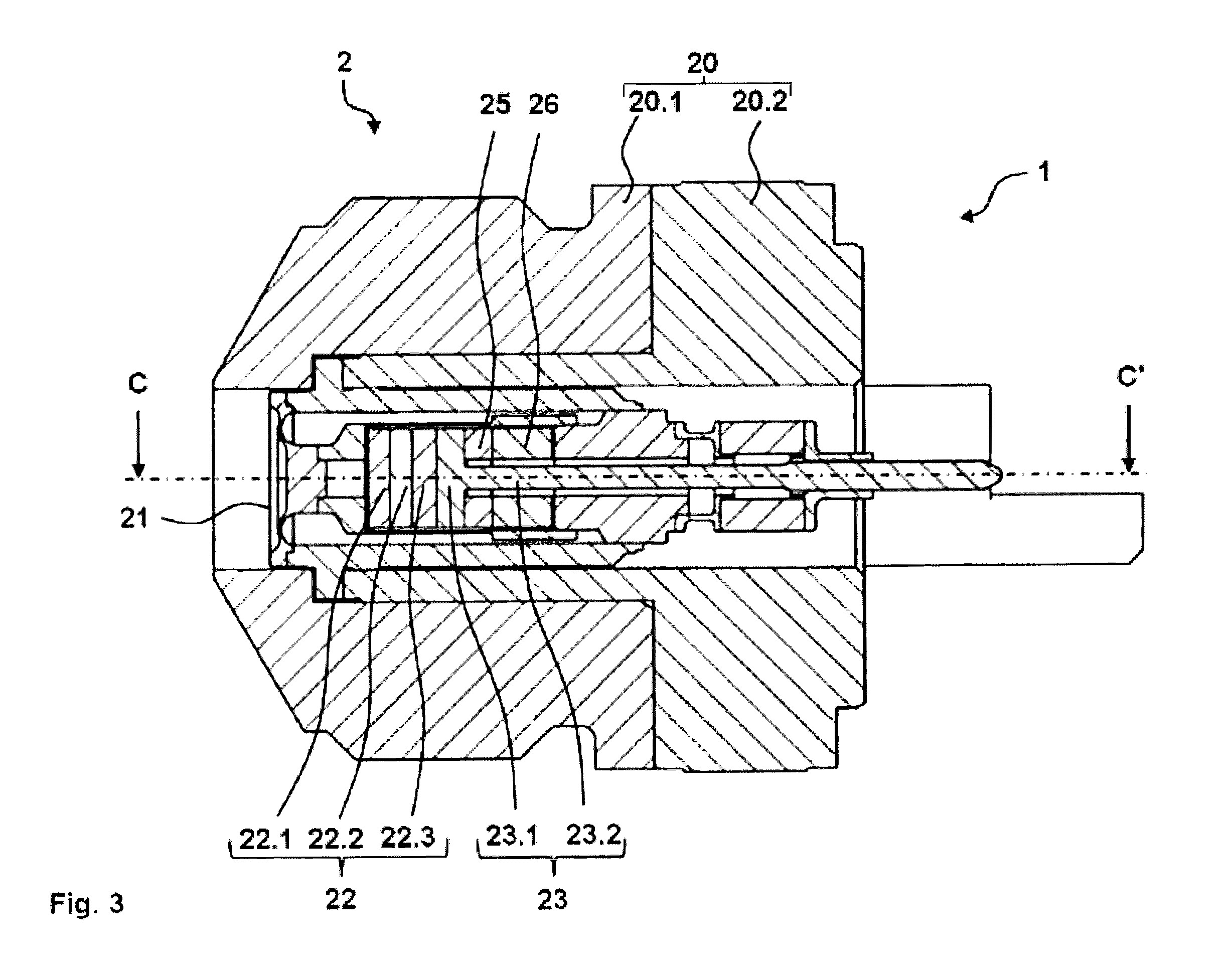
[0027]FIGS. 1 and 2 show sections through two embodiments of the piezoelectric pressure sensor 1 according to the invention. The sections are shown along a longitudinal axis CC′ of the mounted ready-to-use piezoelectric pressure sensor 1. The longitudinal axis CC′, a vertical axis AA′ (FIG. 14) and a horizontal axis BB′ (FIG. 14) are perpendicular to each other. A direction along the longitudinal axis CC′ is called also a longitudinal direction, a direction perpendicular to the longitudinal direction is also called a radial direction. As shown in FIG. 14, the vertical axis AA′ and the horizontal axis BB′ span a radial plane AB. Radial directions lie within the radial plane AB. In cross section, the piezoelectric pressure sensor 1 and its components are generally circular with the center point lying on the longitudinal axis CC′. The adverb “generally” includes a variation from the circular form of ±10%. Knowing the present invention, the piezoelectric pressure sensor and its componen...


PUM


Abstract

A pressure sensor includes an evaluation unit and a sensor assembly, which includes a sensor and an electrode arrangement. The sensor generates signals under the action of a pressure profile, and the electrode arrangement transmits the signals to the evaluation unit, which includes an evaluation unit housing, an electric circuit board and a reinforcement element, which is arranged in a radial plane between the electric circuit board and the evaluation unit housing. The reinforcement element is mechanically connected to the electric circuit board and dampens mechanical resonance vibrations of the electric circuit board that occur in the radial plane.

Description

FIELD OF THE INVENTION[0001]The invention relates to pressure sensors that include a sensor and an evaluation unit connected to the sensor by an electrode arrangement and to a process of manufacturing such pressure sensors.BACKGROUND[0002]Piezoelectric pressure sensors are known and are widely used. Thus, they are used in pressure indexing of internal combustion engines to detect a cylinder pressure prevailing in a pressure chamber as a function of the crankshaft position or a time. Internal combustion engines include four-stroke engines and two-stroke engines such as gasoline engines, diesel engines, Wankel engines, etc. In marine diesel engines, they are used for long-term monitoring of a cylinder pressure. Piezoelectric pressure sensors are used to monitor fast pressure profiles that usually are in the range of 150 to 250 bar but including pressure peaks of 500 bar and higher if pre-ignition and engine knocking occur. However, piezoelectric pressure sensors also can be used in pr...

Claims


Application Information

Patent Timeline
IPC IPC(8): G01L23/10
CPCG01L23/10G01L1/16G01L9/08G01L19/04G01L19/142G01L19/148G01L23/26G01L23/222G01D11/245G01L23/225
Inventor BUCK, REINHOLDGIGER, MARTIN
Owner KISTLER HLDG AG
Learn More