
Method and device for treating a surface

a surface treatment and surface technology, applied in the direction of laser beam welding apparatus, soldering media, abrasive machine components, etc., can solve the problems of affecting the treatment effect, distorting analysis, and not preventing the re-deposition of a part of the waste on the treated surfa

Inactive Publication Date: 2011-09-08
COMMISSARIAT A LENERGIE ATOMIQUE ET AUX ENERGIES ALTERNATIVES
View PDF10 Cites 0 Cited by
  • Summary
  • Abstract
  • Description
  • Claims
  • Application Information

AI Technical Summary

Benefits of technology

[0040]According to one particularly preferable embodiment of the inventive method, the ejection agent is a laser beam due to the many advantages offered by the use of this type of beam in surface treatments and, in particular, the precision with which this treatment can be done, the absence of abrasive effects, and more generally aggressive effects for the surface to be treated, the absence of pollution related to this treatment (no contribution of matter, or gas emanation), and the simplicity of handling a laser.
[0045]Thus, in this particularly preferred embodiment, the aerogel piece or one of the aerogel pieces is preferably arranged opposite the surface to be treated, while being parallel or substantially parallel thereto, and the projection of said piece in the axis of the plume has, in the plane perpendicular to said axis in which this plume has the largest dimensions (i.e. the largest diameter in the event the plasma plume has a circular transverse section), a perimeter in which the perimeter of said plume fits, so as to guarantee trapping of all of the matter ejected from said surface.
[0057]For the same reasons as mentioned above, it is preferable for the means for projecting the ejection agent to be means that make it possible to project a gas, a fluid in supercritical state, dry ice, or electromagnetic radiation.
[0072]the aerogels being very light, the aerogel pieces can, even when they have large dimensions, be easily manipulated and in particular be maintained on attachment arms whereof the mobility can be controlled remotely;
[0074]the aerogels having excellent thermal insulation properties, they can perform, aside from the trapping role, a role of heat screen and as such, thermally protect the projection means of the ejection agent when said means are used inside a heated enclosure and thereby decrease, or even eliminate, the need to use systems aiming to cool said enclosure;
[0075]a certain number of aerogels. being transparent to the visible light, they make it possible to directly view the matter trapped therein.

Problems solved by technology

However, the volumes of liquid used and, therefore, of effluent produced are generally substantial and the operations necessary to isolate the waste from the rest of the effluent, for example if one wishes to analyze it, are expensive.
Moreover, interactions inevitably occur between the waste and the liquid that result in physically and / or chemically modifying this waste and, as a result, distorting the analysis thereof.
However, the use of a gaseous flow to convey the waste does not prevent part of said waste from being redeposited on the treated surface due to the turbulence generated.
Moreover, the filters used at this time must be subjected to relatively heavy treatments if one wishes to extract the waste from them for analysis.
However, such systems are difficult to use in certain mediums and, in particular, in confined or cramped mediums, as well as under certain working conditions such as depression (vacuum) or high temperature conditions.
Moreover, the aspiration noticeably increases the risk of the waste losing its physical integrity and, as a result, distorting the analysis thereof.

Method used


Image

  • Method and device for treating a surface
  • Method and device for treating a surface
  • Method and device for treating a surface

Examples


Embodiment Construction

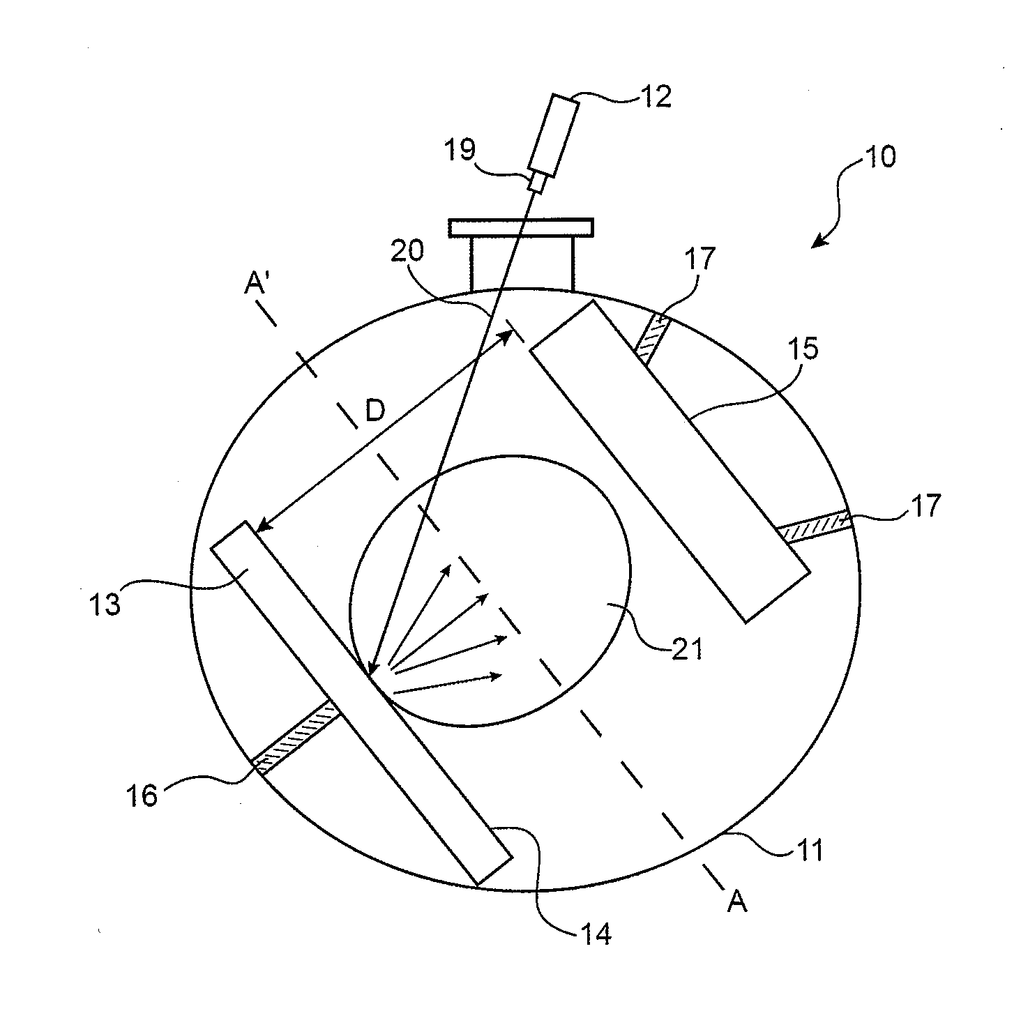
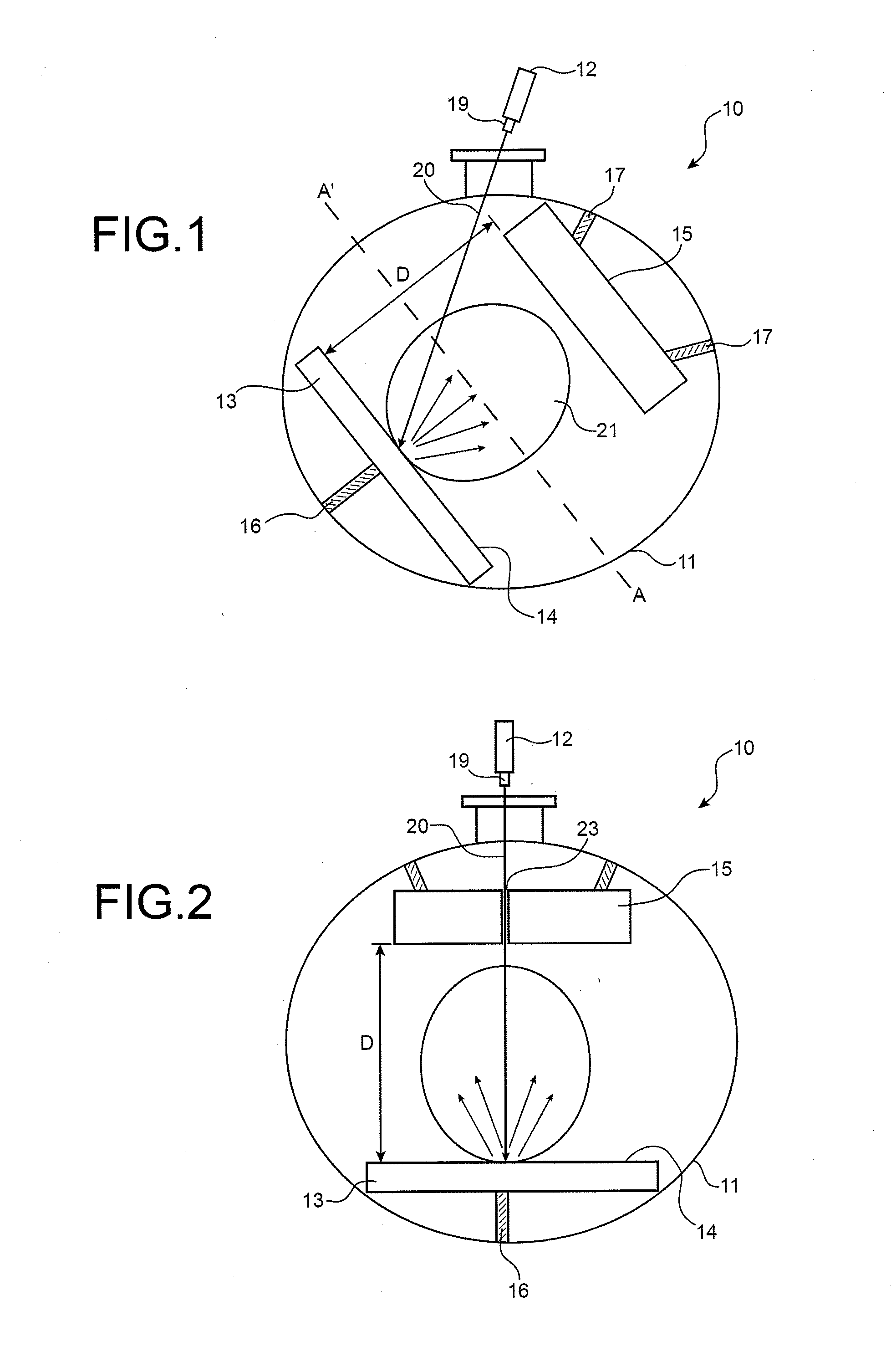
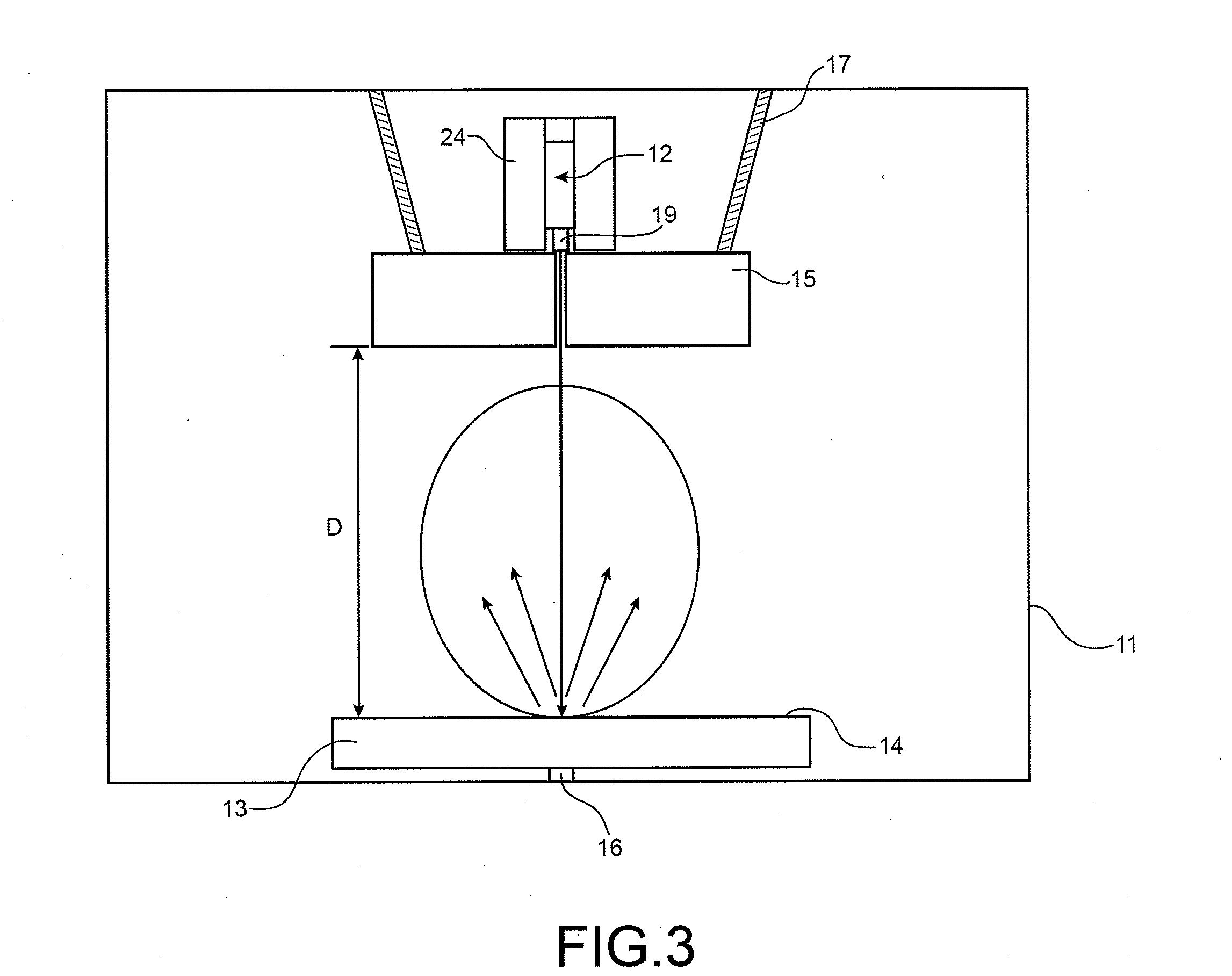
[0082]FIG. 1 shows, diagrammatically and under in use conditions, a first example of a device according to the invention specially designed to treat the surface of an object in a controlled atmosphere enclosure, using a beam emitted by a laser situated outside said enclosure.

[0083]Thus, as shown in this figure, this device 10 comprises, on one hand, an enclosure 11 that is provided with means (not shown in FIG. 1) capable of establishing and maintaining a controlled atmosphere in said enclosure, and, on the other hand, a laser 12 that is arranged outside said enclosure.

[0084]The enclosure 11 contains the object 13 whereof the surface 14 must be treated and, situated opposite said surface and parallel or substantially parallel thereto, a piece of an aerogel 15, with a generally parallelepiped shape.

[0085]The object 13 and the aerogel piece 15 are maintained in the enclosure 11 by maintenance means 16 and 17, respectively, which can consist of any device capable of maintaining an obje...


PUM

PropertyMeasurementUnit
Dimensionaaaaaaaaaa
Wavelengthaaaaaaaaaa
Electromagnetismaaaaaaaaaa

Abstract

A method for treating a surface is disclosed. According to some aspects, the method includes ejecting matter from the surface by projecting an ejection agent on the surface. The ejection agent is selected from gases, fluids in supercritical state, solid materials in divided form,. solid materials in a as vector and electromagnetic radiation. The method includes trapping the ejected matter in one or several pieces of an aerogel situated on trajector of the ejected matter. A device for car in out this method as well as the use of an aerogel to trap the matter ejected from a surface during a treatment of that surface are also disclosed. The method may be applied in fields including cleaning, satinizing, polishing, deburring, etching, marking, pre-adhesion surface preparation metallization enameling, painting or varnishing operations are done, in particular electronics, microelectronics, optics, optoelectronics, bijouterie, jewelry, and the restoration of art and antiques.

Description

TECHNICAL FIELD[0001]The present invention relates to a method for treating a surface, a device making it possible to carry out said method, and the use of an aerogel to trap the matter ejected from a surface during the treatment to which that surface is subjected.[0002]It is applicable in all fields where cleaning, satinizing, polishing, deburring, etching, marking, or surface preparation, e.g. the creation of roughnesses before adhesion, metallization, enameling, painting or varnishing operations are done.[0003]It is more particularly useful in fields where these types of operations are done on pieces that, because they are small or precious or because they have embrittled surfaces, require high-precision treatments.[0004]Such fields are in particular electronics, microelectronics, optics, optoelectronics, bijouterie, jewelry, and the restoration of art and antiques.BACKGROUND OF THE INVENTION[0005]Many surface treatment techniques exist and, in particular, techniques for cleaning...

Claims


Application Information

Patent Timeline
IPC IPC(8): B23K26/00
CPCB23K35/22B24C9/003B24C1/08B24C1/06
Inventor HERNANDEZ, CAROLINE
Owner COMMISSARIAT A LENERGIE ATOMIQUE ET AUX ENERGIES ALTERNATIVES
Learn More