Internal combustion piston engine with an adjustable inflating element

a technology of inflating element and internal combustion piston, which is applied in the direction of valve details, non-fuel substance addition to fuel, exhaust gas recirculation, etc., can solve the problems of high structural complexity, high cost, and strong pressure fluctuations, and achieves low cost and simple measures

Inactive Publication Date: 2011-09-15
SCHAEFFLER TECH AG & CO KG
View PDF11 Cites 15 Cited by
  • Summary
  • Abstract
  • Description
  • Claims
  • Application Information

AI Technical Summary

Benefits of technology

[0007]It is therefore the object of the invention to improve an internal combustion piston engine with the initially described features, so as to provide an effective engine brake through intermittent opening of one or more exhaust valves in the region of the upper dead center of the internal combustion piston engine, which brake must be realizable through simple measures and low costs. In addition, this should be accomplished in connection with components of a hydraulic lash adjusting element. Moreover, valve lash must be adjustable in a simple manner.
[0012]In an advantageous development of the invention, the spacers are configured as ball sockets which are operatively connected to a ball head of a working piston. Through the use of a ball socket and a ball head, undesired surface pressures are avoided. Moreover, ball sockets possess the advantage that they can be fixed safe against loss on the ball head of the working piston of the inflating element, and the bridge or the valve stem does not require any additional receptions.
[0014]When the control piston is loaded with reduced oil pressure, the spring presses the control piston against the valve body of the non-return valve, which is preferably configured as a ball, and opens this. As a result, the control element can get shortened, so that the additional cam is inactive and no compression relief opening of the exhaust valve or valves takes place. The non-return valve, however, still remains active so that no uncontrolled lash is produced in the region of the base circle of the exhaust valve and no uncontrolled vibrations of the transmitting elements occur. The finger lever or rocker arm, if necessary also an installed tappet, is therefore in constant contact with the additional cam. The additional lift, however, is suppressed in this case by the inflating element.

Problems solved by technology

A drawback of this configuration is that the oil pressure is used directly for the actuation of the piston, so that a high pressure or a larger piston cross-section is required and strong pressure fluctuations can occur.
Furthermore, the additional valve lash adjusting screw is considered as a drawback because, irrespective of the additional complexity and expense caused by the thread and the like, it constitutes an undesired additional mass.
The required structural complexity for extending and retracting the additional cams is considerably high and cost-intensive and therefore considered as a drawback.

Method used


Image

  • Internal combustion piston engine with an adjustable inflating element
  • Internal combustion piston engine with an adjustable inflating element
  • Internal combustion piston engine with an adjustable inflating element

Examples


Embodiment Construction

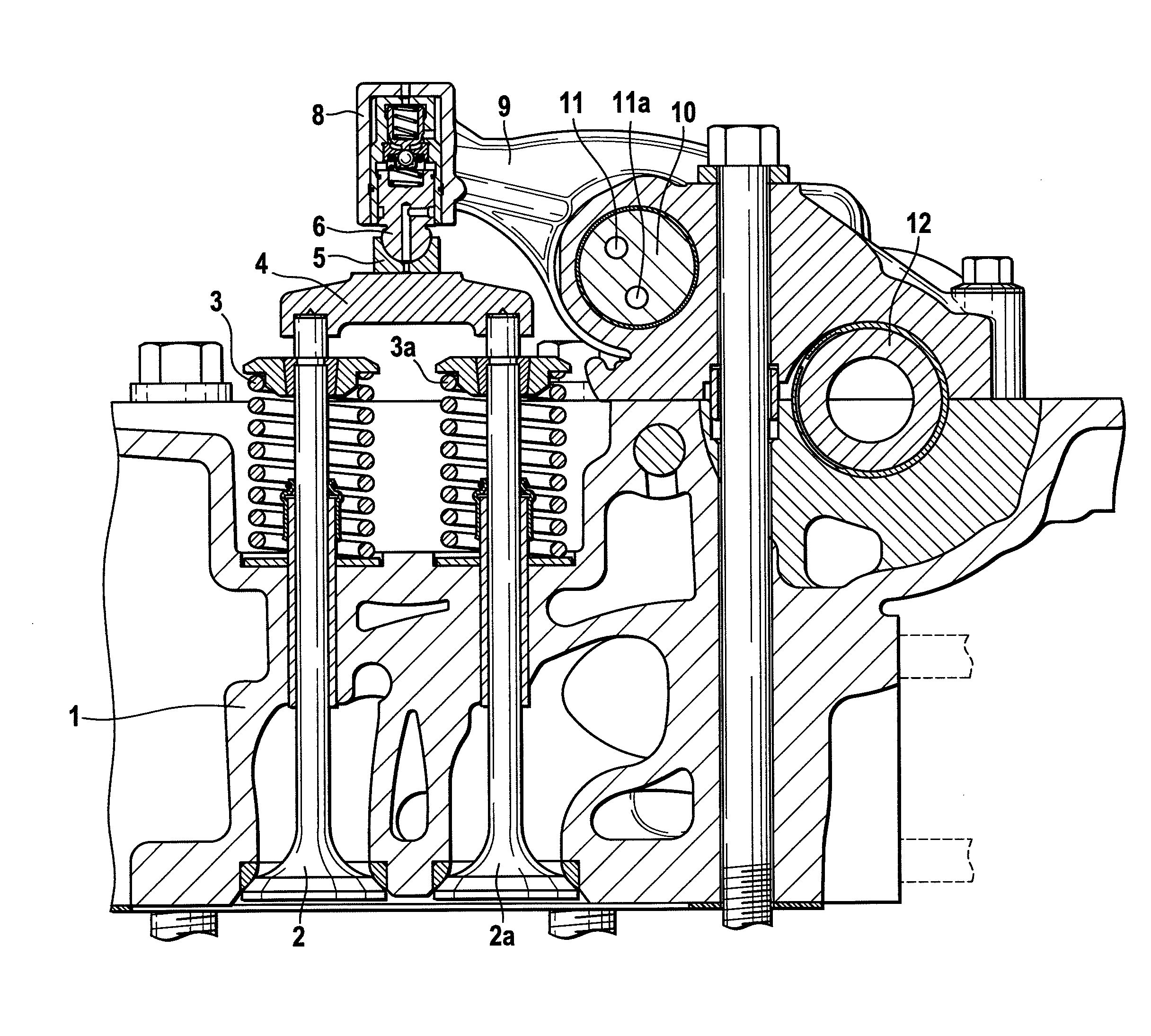
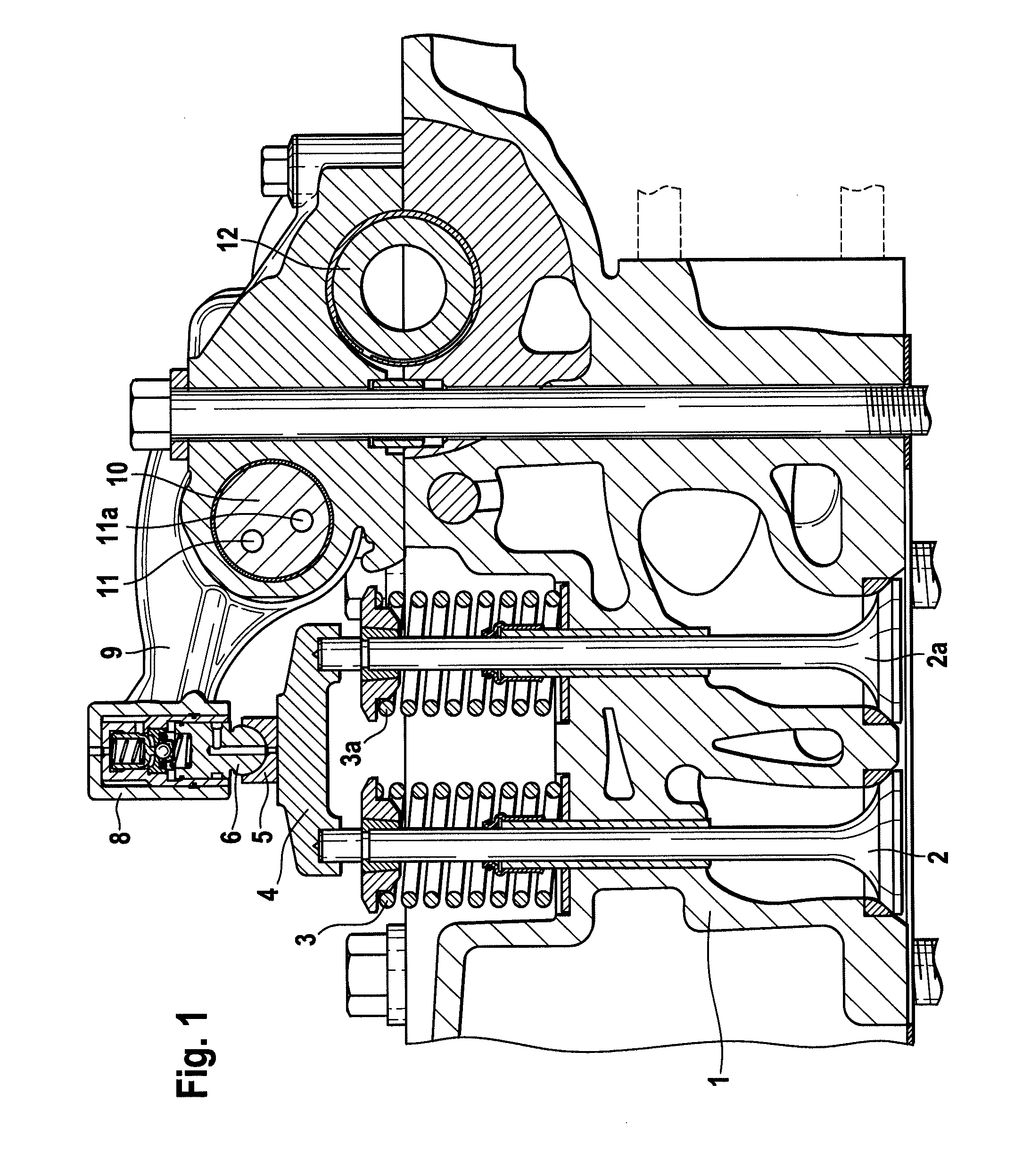
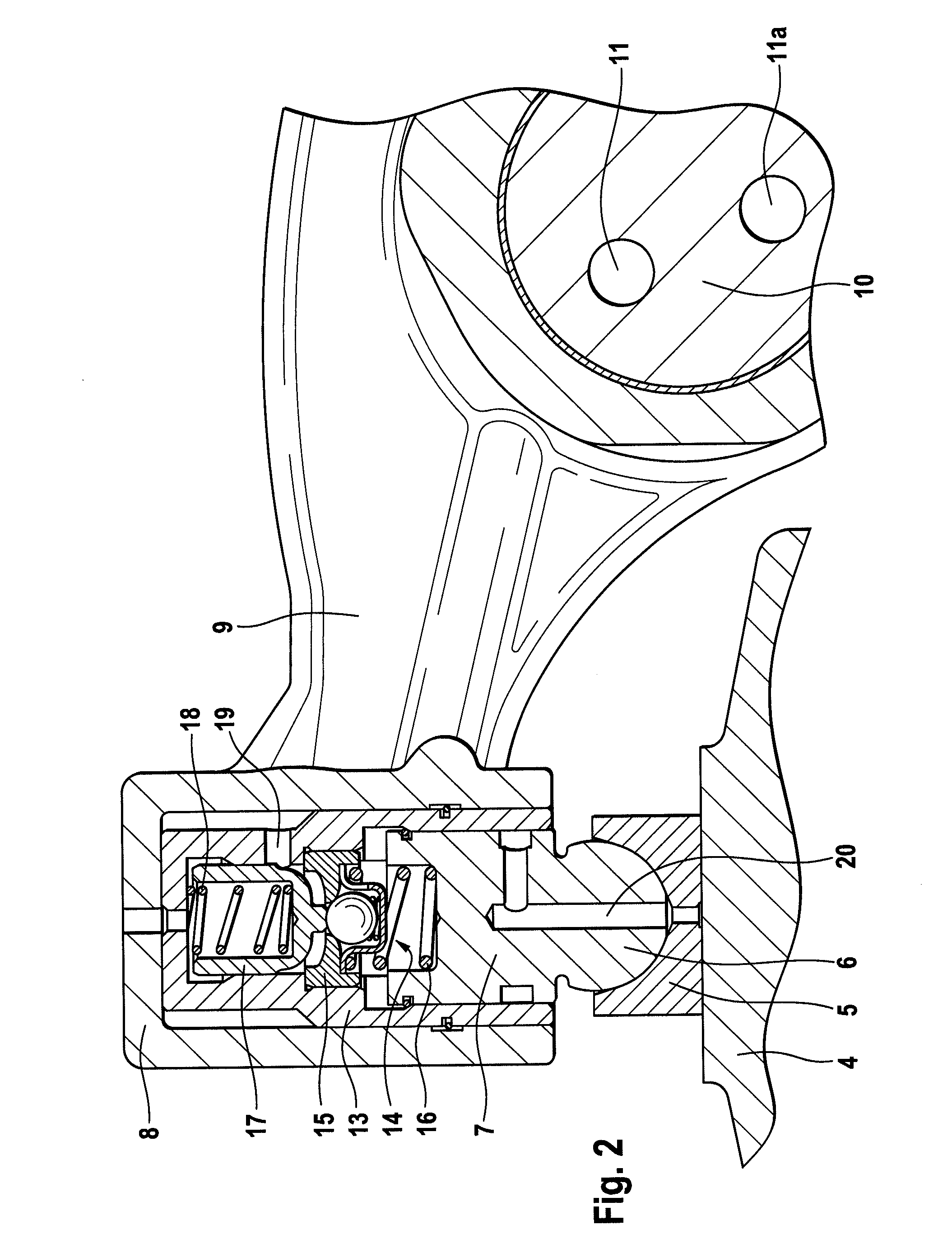
[0019]In FIGS. 1 and 2 a cylinder head of an internal combustion piston engine, as far as specifically shown, is identified at 1. The exhaust channels of the engine are controlled by two exhaust valves 2 and 2a that are guided in the cylinder head 1 and biased in closing direction by valve springs 3 and 3a. A bridge 4 is associated to the valve stems of the exhaust valves 2 and 2a and engages around the ends of the valve stems while being operatively connected to a ball socket 5 supported on a ball head 6 of a working piston 7 which is a component part of an inflating element generally identified at 8. The inflating element 8 is installed in a recess of a rocker arm 9 and supplied with oil from an oil bore in the rocker arm 9, not specifically shown. The rocker arm 9 is mounted on an axle 10 comprising oil channels 11 and 11a which are connected to the oil circulation of the internal combustion piston engine. The oil pressure delivered to the inflating element 8 can be varied throug...


PUM


Abstract

An internal combustion piston engine based on a four-stroke process, having a crankcase in which at least one cylinder / piston assembly is arranged, the piston being guided by a connecting rod connected to a crankshaft. At least one cylinder head (1) closes the cylinder, each of whose intake and exhaust channels are controlled by at least one intake valve and at least one exhaust valve (2, 2a). The intake and exhaust valves are actuable by a finger lever or a rocker arm driven by a camshaft (12) through intake and exhaust cams. The finger levers or rocker arms are guided on at least one axle (10). At least one additional cam is provided in the region of the base circle of the outlet cam for an additional opening of the at least one exhaust valve (2, 2a), and a control element is installed between the finger lever or rocker arm and the exhaust valve or valves (2, 2a), which control element can be connected to a pressure oil source and has a variable length, so that the additional cam is active during a compression relief operation and inactive during a pure engine operation. The control element is configured as an inflating element (8) and is operatively connected through a working piston (7), with interposition of a spacer, to a bridge (4) associated to a plurality of exhaust valves (2, 2a), or is operatively connected to a valve stem of an exhaust valve.

Description

CROSS-REFERENCE TO RELATED APPLICATIONS[0001]This application claims the benefit of German Patent Application No. 102010011455.3, filed Mar. 15, 2010, which is incorporated herein by reference as if fully set forth.FIELD OF THE INVENTION[0002]An internal combustion piston engine based on a four-stroke process, comprising a crankcase in which at least one cylinder / piston assembly is arranged, the piston being guided by a connecting rod connected to a crankshaft, further comprising at least one cylinder head for closing the cylinder, each of whose intake and exhaust channels are controlled by at least one intake valve and one exhaust valve, said intake and exhaust valves being actuable by a finger lever or a rocker arm driven by a camshaft through intake and exhaust cams, the finger levers or rocker arms being guided on at least one axle, further comprising at least one additional cam in the region of the base circle of the outlet cam for an additional opening of at least one exhaust ...

Claims


Application Information

Patent Timeline
Patent Type & Authority Applications(United States)
IPC IPC(8): F01L1/18
CPCF01L1/08F01L1/2411F01L1/267F02M25/0752F01L13/085F01L2105/00F01L2800/10F01L13/065F02M26/01F01L2305/00
Inventor SAILER, PETERSCHNELL, OLIVERWITTER, OLIVER
Owner SCHAEFFLER TECH AG & CO KG
Why Eureka
Try Eureka