
Pneumatic tire

a technology of pneumatic tires and blocks, applied in the field of pneumatic tires, can solve the problems of increasing the collision noise of blocks with the road surface, tire noise is collision noise, etc., and achieves the effects of enhancing block stiffness, reducing collision noise of blocks, and effective improving wear resistan

Inactive Publication Date: 2011-09-15
BRIDGESTONE CORP
View PDF6 Cites 10 Cited by
  • Summary
  • Abstract
  • Description
  • Claims
  • Application Information

AI Technical Summary

Benefits of technology

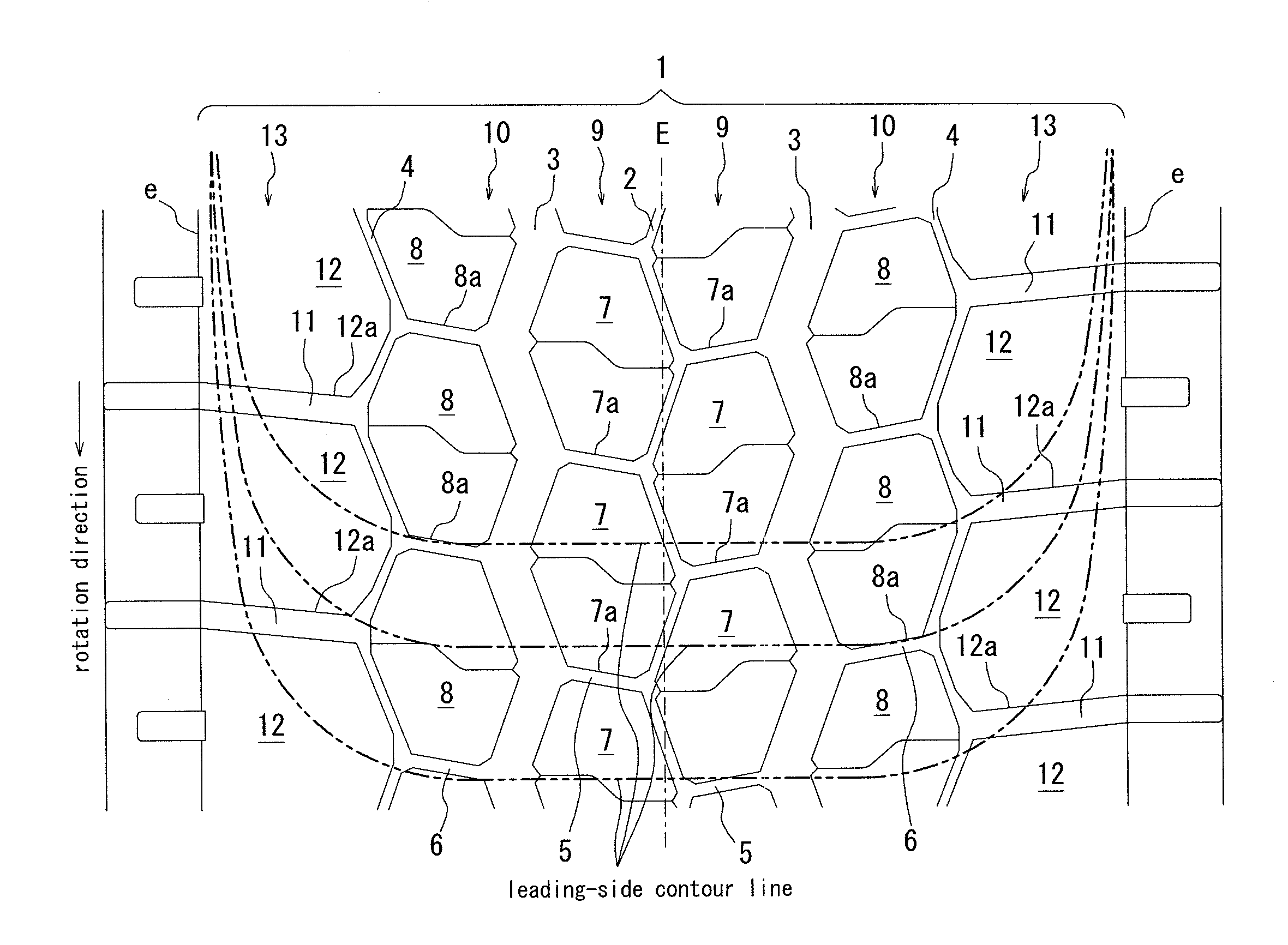
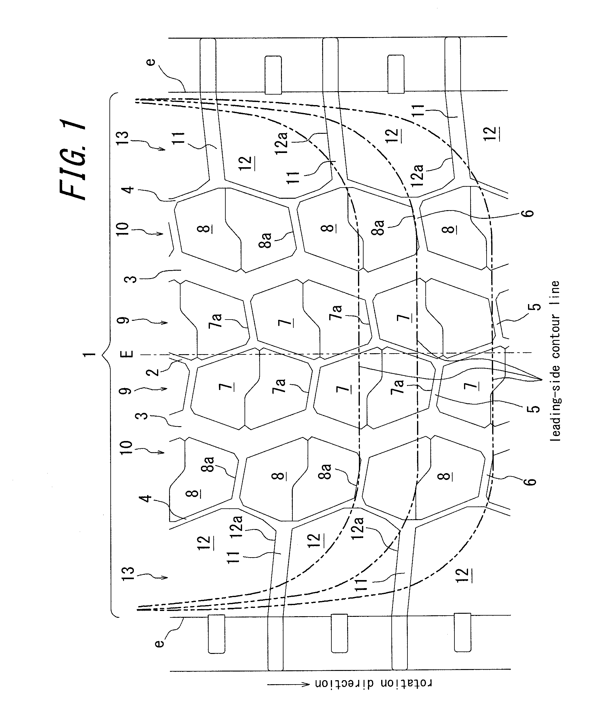
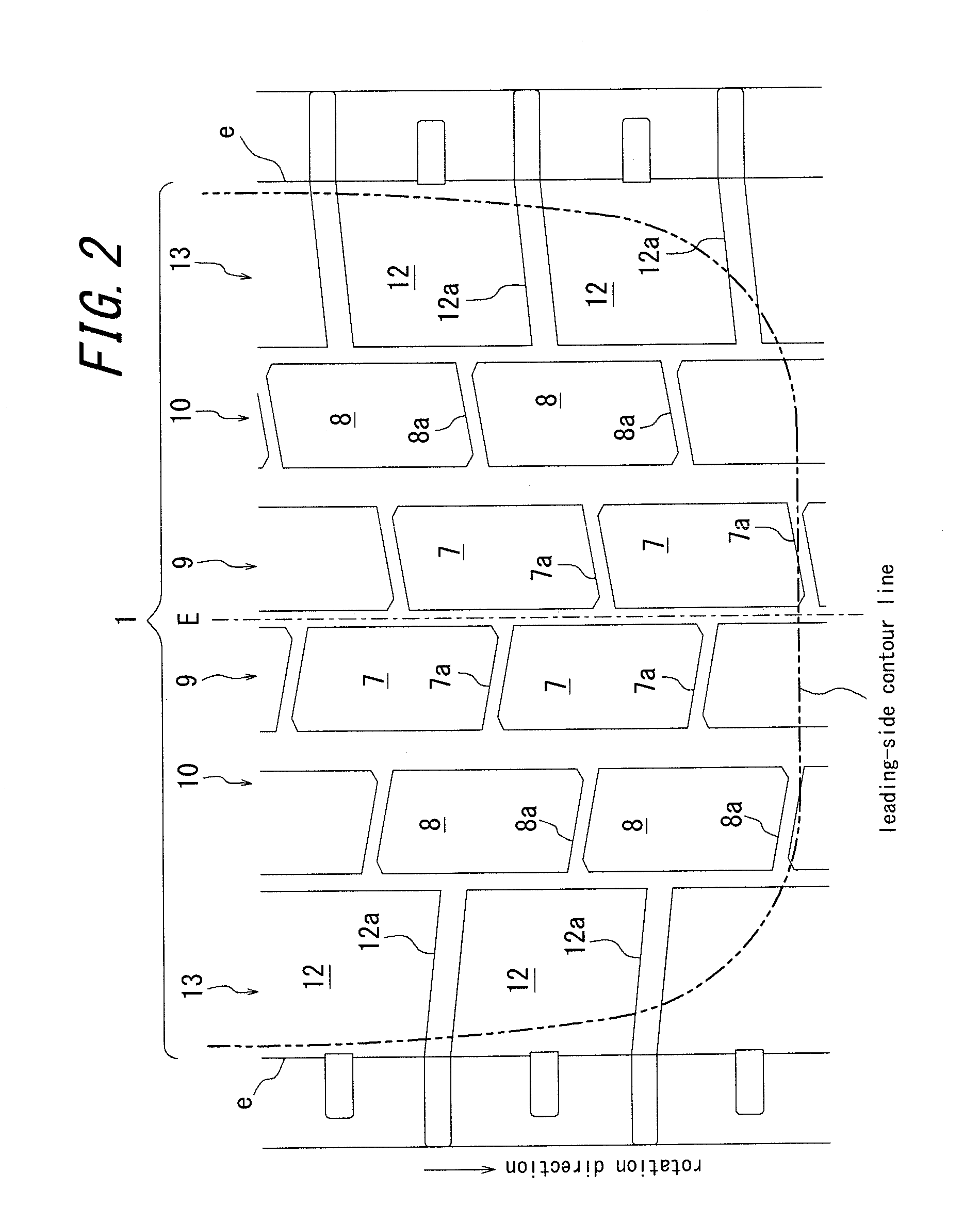
[0016]In the pneumatic tire of this invention, it is possible to reduce collision noise of blocks with a road surface in comparison to that of conventional tire by spacing the leading edges of the blocks of each rows when the tire is rolling under load from each other in the tread circumferential direction since the leading edge of the block of each block row collides with a road surface one by one with the timing being delayed with each other and a plurality of block leading edges do not collide with a road surface simultaneously.
[0017]This is further effective when each lateral groove is inclined with respect to the tread widthwise direction and the corner portion to be the leading-side end portion of each block collides with a road surface as a dot, which is much shorter than a line.
[0018]In addition, it is possible to enhance block stiffness and effectively improve wear resistance by making each of the blocks have a polygon planar contour shape with six or more sides such that a minimum length of the block in the tread widthwise direction is situated in leading-side and / or trailing-side end portion of the block in the tread circumferential direction and a middle portion of the block in the tread circumferential direction has a length greater than the length of the end portion in the tread circumferential direction and by further increasing the width of the middle portion and the like in the tread circumferential direction.
[0019]When each of the blocks has, for example, a hexagon planar contour shape with each side being a convex curve and / or a concave curve, as described in JP2007-145209 and Japanese Patent Application No. 2007-140896 previously filed by the applicant, it is possible to reduce uneven sliding of the blocks in the tread width and circumferential directions, improve uneven wear resistance and improve wear resistance. When a groove center of each of the lateral grooves has an inclination angle of 5 degrees to 30 degrees with respect to the tread widthwise direction, as to each block defined by the lateral grooves having a constant width over their entire length, heel and toe uneven wear can be advantageously suppressed caused by local sliding of the block trailing-side portion with respect to a road surface and hammering noise caused by collision of the block leading edge with a road surface can be effectively prevented by reducing the length of the leading edge colliding with a road surface simultaneously.
[0020]In other words, in case when the inclination angle of the lateral groove is less than 5 degrees, effective reduction of collision noise of the block leading edge with a road surface is difficult to be achieved. In case when the inclination angle is more than 30 degrees, local and early wear of the block trailing-side portion cannot be prevented.
[0021]The above-mentioned effect is further achieved when the tread pattern comprising the blocks is a directional pattern and when a normal rotation direction of the tire, in turn the leading-side portion and trailing-side potion of each block are specified.

Problems solved by technology

For a conventional pneumatic tire, for example, having a block pattern, one of tire noise is collision noise caused when a leading edge of a block collides with a road surface when the tire is rolling under load.
However, even in this case, when the same pitch variation is adopted to the entire width of the tread surface, blocks are symmetrically arranged with respect to a tire equator line and the leading edges of several blocks collide with a road surface simultaneously when the tire is rolling under load, which results in increase of collision noise of the blocks with a road surface.

Method used


Image

  • Pneumatic tire
  • Pneumatic tire
  • Pneumatic tire

Examples


example

[0042]Conventional tire, Comparative Example tires and Example tires having a size of 315 / 80R22.5 are prepared and each tire is mounted to a rim of 9.00×22.5, inflated with an air pressure of 650 kPa, applied with load of 2800 kgf and evaluated for a vehicle pass-by noise examination under a condition (LI=156 condition) based on European noise regulation.

[0043]LI (load index)=156 condition as used herein means a condition of category C3 (mainly TBR) of TRANS / WP.29 / 2002 / 7 18 Dec., 2001 additional clause 3 by the united regulation of the tire authorization concerning tire noise of The United Nations and Economic Commission for Europe (ECE).

[0044]The results and the specifications of the tires are shown in Table 1.

[0045]Conventional tire has a tread pattern shown in FIG. 4 and both of Comparative Example tires and Example tires have a tread pattern shown in FIG. 1 as a basic pattern.

[0046]The tire inflated with an air pressure of 850 kPa is attached to a drive shaft of a tractor, to wh...


PUM


Abstract

The present invention is directed to provide a pneumatic tire capable of effectively preventing large collision noise due to simultaneous collision of plural blocks of respective rows with a road surface. Six rows 9, 10, 13 of blocks on a tread surface 1 are defined by five circumferential grooves 2, 3, 4 continuously extending in a tread circumferential direction in a zigzag manner, a plurality of lateral grooves 5, 6, 11 extending in a tread widthwise direction between the circumferential grooves adjacent to each other and between the outermost circumferential grooves 4 and respective tread side edges e. Five circumferential grooves 2, 3, 4 comprise narrow circumferential grooves 2, 4 and a pair of wide circumferential grooves 3 disposed on each side of the tire equator line and having a width greater than that of the narrow circumferential grooves 2, 4. The lateral grooves 5, 6 are inclined with respect to the tread widthwise direction. Each of the blocks 7, 8, 12 of the block rows 9, 10, 13 has a polygon planar contour shape with six or more sides such that a minimum length of the block in the tread widthwise direction is situated in an end portion of the block in the tread circumferential direction and a middle portion of the block in the tread circumferential direction has a length greater than the length of the end portion in the tread circumferential direction. Leading edges 7a, 8a, 12a of the blocks 7, 8, 12 of each rows 9, 10, 13 when the tire is rolling under load are spaced from each other in the tread circumferential direction.

Description

TECHNICAL FIELD[0001]The present invention relates to a pneumatic tire and particularly to a technique to reduce noise generated due to collision of blocks defined on a tread surface with a road surfaceRELATED ART[0002]For a conventional pneumatic tire, for example, having a block pattern, one of tire noise is collision noise caused when a leading edge of a block collides with a road surface when the tire is rolling under load. Conventionally, pitch variation is widely adopted in order to change such collision noise and the like to white noise.[0003]However, even in this case, when the same pitch variation is adopted to the entire width of the tread surface, blocks are symmetrically arranged with respect to a tire equator line and the leading edges of several blocks collide with a road surface simultaneously when the tire is rolling under load, which results in increase of collision noise of the blocks with a road surface.DISCLOSURE OF THE INVENTIONProblems to be Solved by the Inven...

Claims


Application Information

Patent Timeline
Patent Type & Authority Applications(United States)
IPC IPC(8): B60C11/13
CPCB60C11/0306B60C11/11B60C11/0332
Inventor MATSUZAWA, KAZUTAKA
Owner BRIDGESTONE CORP
Learn More