Electrostatic relay

a technology of electrostatic relay and electrostatic inclination, which is applied in the direction of emergency protection devices, contacts, emergency actuators, etc., can solve the problems of degrading the design freedom, and achieve the effect of simplifying and miniaturizing the structure of the electrostatic relay and avoiding the risk of inclination of the movable portion

Inactive Publication Date: 2011-09-15
ORMON CORP
View PDF11 Cites 13 Cited by
  • Summary
  • Abstract
  • Description
  • Claims
  • Application Information

AI Technical Summary

Benefits of technology

[0019]In the electrostatic relay according to one or more embodiments of the present invention, second spring members are provided at positions that are symmetrical in relation to a center line of the movable electrode portion. Accordingly, because the second spring members are symmetrically provided, a force applied to the movable portion becomes asymmetric after the fixed portion or the movable portion abuts on the second spring member, and there is no risk of inclining the movable portion.
[0020]In the electrostatic relay according to one or more embodiments of the present invention, the first spring members are provided in both end faces in the direction in which the movable electrode portion is displaced, or the first spring members are provided opposite the end faces, respectively. Accordingly, because the movable electrode portion can float from the base substrate by retaining the movable electrode portion from both sides with the first spring member, the movable electrode portion can be stabilized.
[0021]In the electrostatic relay according to one or more embodiments of the present invention, the first spring member is provided in one of end faces in the direction in which the movable electrode portion is displaced, or the first spring member is provided opposite one of the end faces. Accordingly, because the first spring member is provided only on one side of the movable electrode portion, the structure of the electrostatic relay can be simplified and miniaturized.

Problems solved by technology

In the electrostatic relay, although the original spring modulus of the movable spring can arbitrarily be increased by a position or a height of the projection portion, there is a restriction to the position or the height, and a degree of freedom of design is degraded by processing preciseness or troublesome design.

Method used


Image

  • Electrostatic relay
  • Electrostatic relay
  • Electrostatic relay

Examples


first embodiment

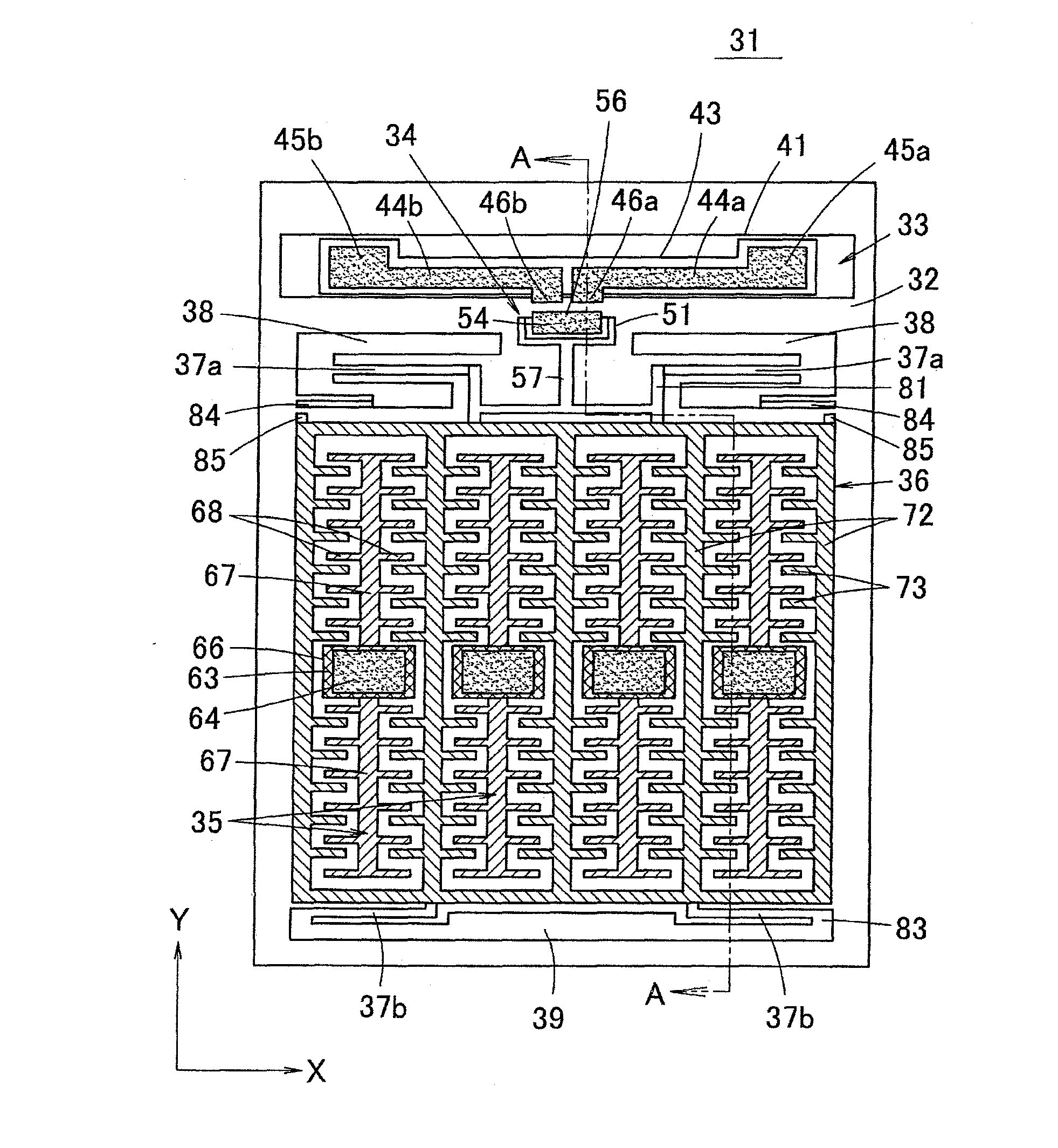
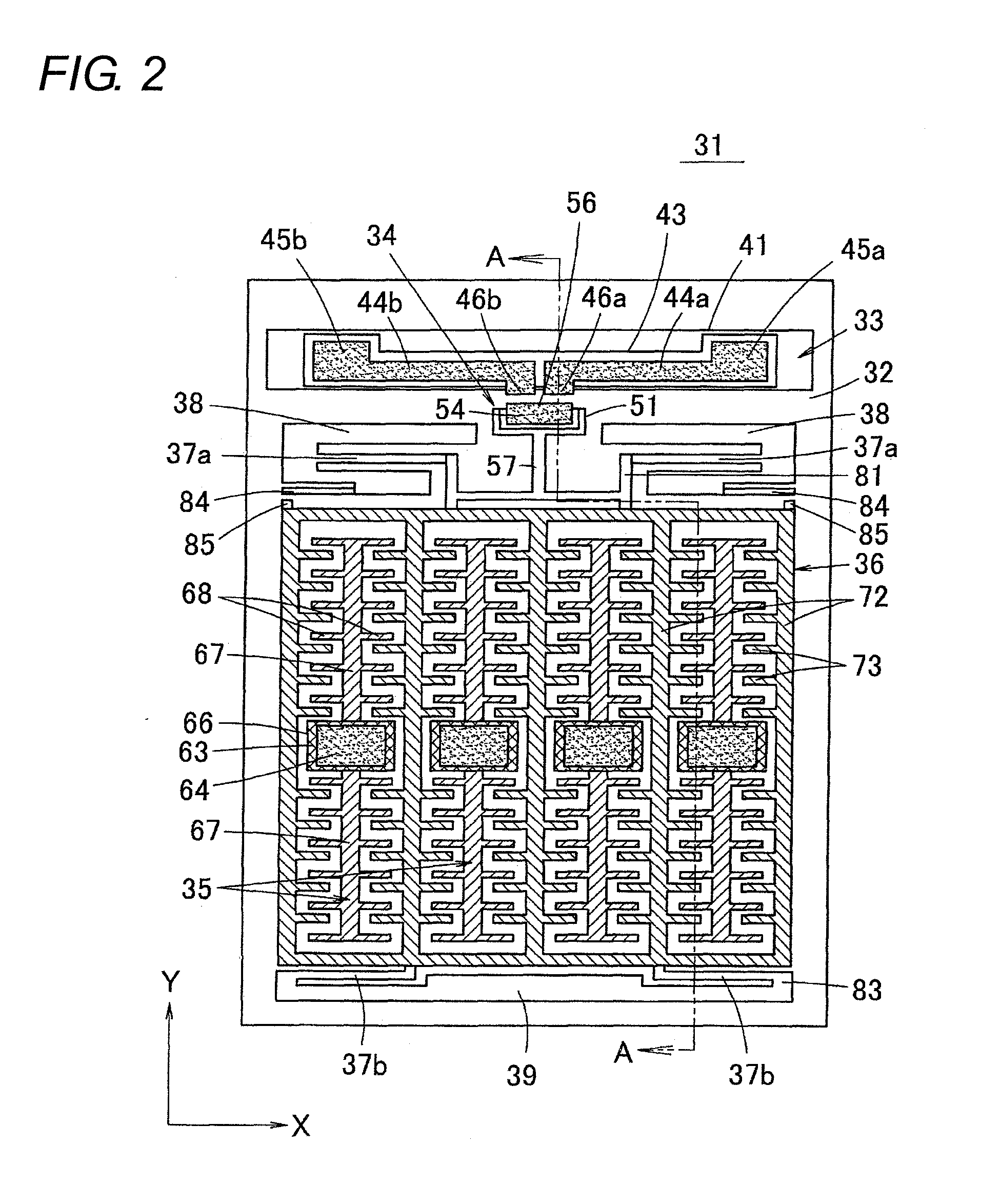
[0032]FIG. 2 is a plan view showing a structure of an electrostatic relay 31 according to a first embodiment of the present invention. FIG. 7B is a sectional view taken on a line A-A of FIG. 2. The structure of the electrostatic relay 31 will be described with reference to FIGS. 2 and 7B.

[0033]A fixed contact portion 33, a moving contact portion 34, a fixed electrode portion 35, a movable electrode portion 36, movable springs 37a and 37b (first spring member), and spring supporting portions 38 and 39 are provided in an upper surface of a base substrate 32 formed by an Si substrate in the electrostatic relay 31. In the electrostatic relay 31, a switch is formed by the fixed contact portion 33 and the moving contact portion 34, and an electrostatic actuator for opening and closing the switch is formed by the fixed electrode portion 35, the movable electrode portion 36, the movable springs 37a and 37b, and the spring supporting portions 38 and 39.

[0034]As shown in FIGS. 2 and 7B, in th...

second embodiment

[0068]FIG. 9 is a plan view showing a structure of an electrostatic relay 111 according to a second embodiment of the present invention. In the electrostatic relay 111, a movable spring 37a is provided in a fixed-fixed beam manner in the spring supporting portion 38, and the coupling portion 81 that is projected from the front end portion of the movable electrode portion 36 is coupled to the central portion of the movable spring 37a. In the structure of the electrostatic relay 111, the movable spring 37a constitutes the fixed-fixed beam, so that the spring modulus of the movable spring 37a can be increased.

[0069](Other Modifications)

[0070]In the first and second embodiments, the movable springs 37a and 37b that support the movable electrode portion 36 are provided in the front end face and rear end face of the movable electrode portion 36. Alternatively, only one of the movable springs 37a and 37b may be provided in the front end face or rear end face of the movable electrode portio...


PUM


Abstract

In an electrostatic relay in which a moving contact and a movable electrode are displaced in parallel with a base substrate, an opening force is increased when the movable electrode is separated from a fixed electrode, and a structure is simplified to enhance a degree of freedom of design. A fixed contact portion and a fixed electrode portion are fixed to the base substrate. The fixed electrode portion and a movable electrode portion constitute an electrostatic actuator that displaces the movable electrode portion and a moving contact portion. A movable spring provided in a spring supporting portion retains the movable electrode portion in a displaceable manner. A cantilever secondary spring is provided in the spring supporting portion, and a projection portion is provided in a front end face of the movable electrode portion. The secondary spring abuts on the projection portion while being not deformed until abutting on the projection portion, before the moving contact of the moving contact portion abuts on the fixed contact of the fixed contact portion when the moving contact portion and the movable electrode portion are displaced.

Description

BACKGROUND OF THE INVENTION[0001]1. Technical Field[0002]The present invention relates to a compact electrostatic relay (electrostatic micro-relay), specifically to a structure of a secondary spring that elastically restores a movable portion in an electrostatic relay.[0003]2. Related Art[0004]In the electrostatic relay, when a moving contact is brought into contact with a fixed contact, an electrostatic actuator is driven to displace the moving contact. When the moving contact and the fixed contact are separated from each other, the moving contact is separated from the fixed contact by an elastic restoring force of a movable spring that is elastically deformed in driving the electrostatic actuator.[0005]In driving the electrostatic actuator, a DC voltage is applied between a movable electrode and a fixed electrode, and the movable electrode is attracted to the fixed electrode by an electrostatic force that acts between the electrodes, thereby displacing a member in which the movabl...

Claims


Application Information

Patent Timeline
Patent Type & Authority Applications(United States)
IPC IPC(8): H01H59/00
CPCH01H2001/0078H01H59/0009H01H45/14H01H2221/036H01H2235/02H01H2239/008
Inventor MASUDA, TAKAHIROYAMAMOTO, JUNYA
Owner ORMON CORP
Why Eureka
Try Eureka