Process for forming a vessel

Active Publication Date: 2011-09-15
GM GLOBAL TECH OPERATIONS LLC
View PDF10 Cites 27 Cited by
  • Summary
  • Abstract
  • Description
  • Claims
  • Application Information

AI Technical Summary

Benefits of technology

[0005]In accordance and congruent with the present invention, a vessel and a method for producing the vessel including a hollow liner an

Problems solved by technology

The weld seams, however, may not be fluid-tight and permit permeation of the stored fluid from the vessel.
Further, the welding process limits the types of material which can be used to form the liner.
On the other hand, the rotational molding process is slower and produces a liner having an adverse thickness.
The bosses, however, may not prope

Method used


Image

  • Process for forming a vessel
  • Process for forming a vessel
  • Process for forming a vessel

Examples


Embodiment Construction

[0013]The following detailed description and appended drawings describe and illustrate various exemplary embodiments of the invention. The description and drawings serve to enable one skilled in the art to make and use the invention, and are not intended to limit the scope of the invention in any manner. In respect of the methods disclosed, the steps presented are exemplary in nature, and thus, the order of the steps is not necessary or critical.

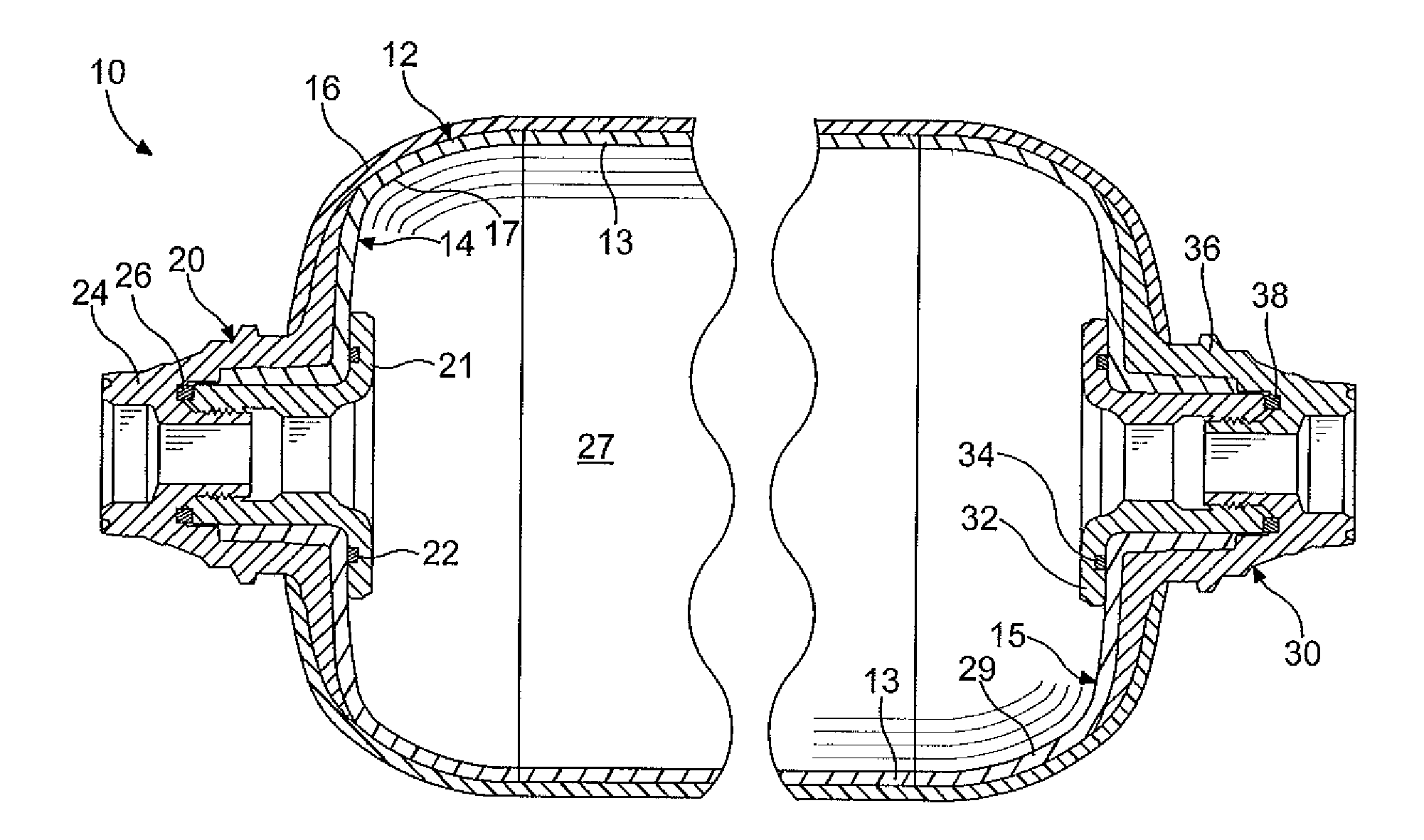
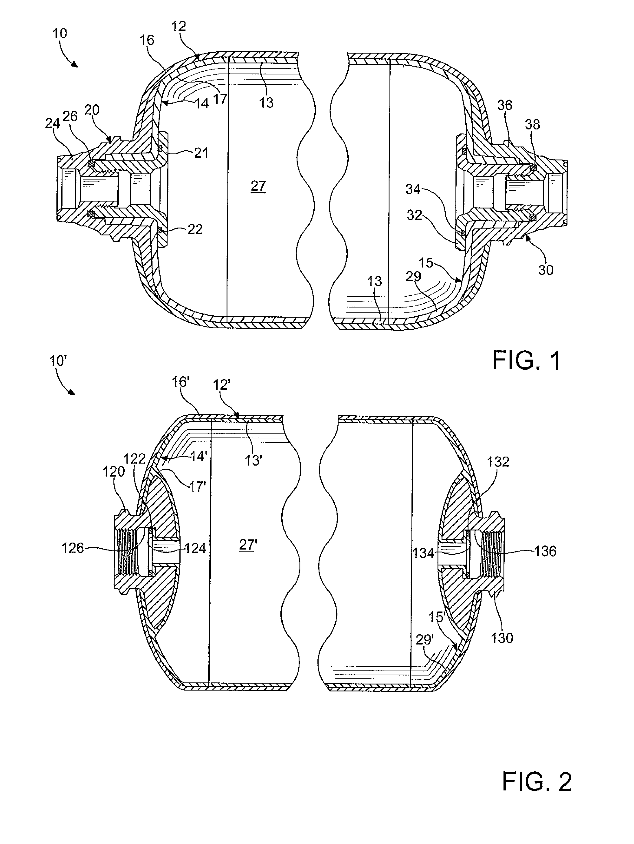
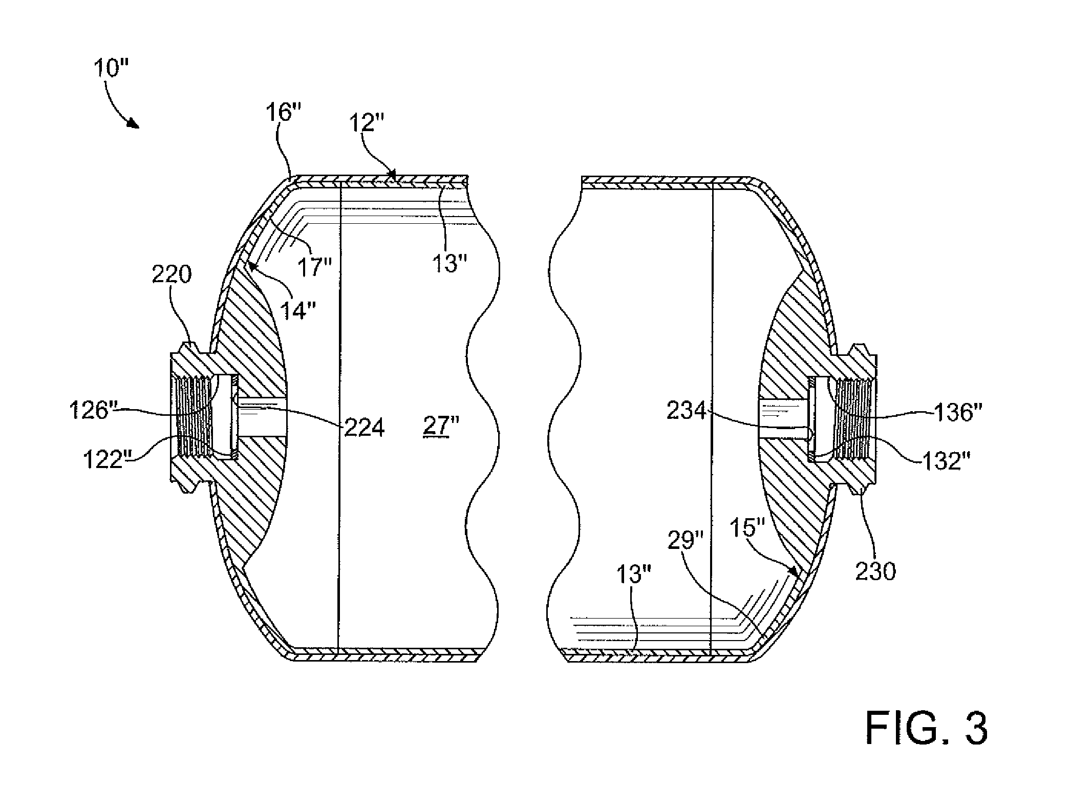
[0014]FIG. 1 illustrates a vessel 10. The vessel 10 includes a hollow liner 12 having a thin main body 13, a first end cap 14, and a second end cap 15. In the embodiment shown, the vessel 10 further includes an outer shell 16. The vessel 10 has a substantially cylindrical shape and is adapted to hold a pressurized fluid (not shown). It is understood that the vessel 10 may have any shape as desired, and the vessel 10 may include additional layers such as a barrier layer, a foil layer, a porous permeation layer, and the like, as desired. The p...


PUM


Abstract

A vessel and method for forming the vessel is disclosed, the vessel having a hollow liner, at least one boss, and a filament wound outer shell, wherein at least a portion of the hollow liner if formed by at least one of an co-extrusion blow film molding process, a thermoplastic foiling process, and a coating process.

Description

FIELD OF THE INVENTION[0001]The invention relates to a vessel and more particularly to a pressure vessel and a method for forming the vessel, wherein the vessel includes a hollow liner formed from an extruded film tube and a pair of end caps.BACKGROUND OF THE INVENTION[0002]Presently, there are a variety of vessels designed to contain various fluids such as compressed natural gas (CNG), hydrogen gas for use in a fuel cell, and the like, for example. A common technique for storing the fluid is in a lightweight, high pressure vessel resistant to punctures. Traditionally, such vessels are divided into four types. A Type I vessel is a metal vessel. A Type II vessel is also a metal vessel, the vessel having an outer composite shell disposed on a cylindrical section thereof. A Type III vessel consists of a liner produced from a metal such as steel and aluminum, for example, and an outer composite shell that encompasses the liner and militates against damage thereto. A Type IV vessel is su...

Claims


Application Information

Patent Timeline
IPC IPC(8): F17C1/02B31B1/90
CPCF17C1/06Y02E60/321F17C2201/056F17C2203/0604F17C2203/0607F17C2203/0619F17C2203/0624F17C2203/0636F17C2203/066F17C2203/0663F17C2203/0673F17C2205/0305F17C2205/0323F17C2205/0397F17C2209/2127F17C2209/234F17C2221/011F17C2221/012F17C2221/033F17C2223/0123F17C2223/013F17C2223/0153F17C2223/035F17C2223/036F17C2201/0109Y02E60/32
Inventor STRACK, LUDGER
Owner GM GLOBAL TECH OPERATIONS LLC
Why Eureka
Try Eureka