Winding insulation arrangement for axial flux machines

a technology of winding insulation and axial flux, which is applied in the field of electric machines, can solve the problems of unnecessarily including winding materials, difficult to achieve good, and high cost of winding process, so as to reduce the length of turn reduce the use of material and cost, and reduce the resistance of the winding coil

Inactive Publication Date: 2011-09-15
REGAL BELOIT AUSTRALIA PTY LTD
View PDF6 Cites 23 Cited by
  • Summary
  • Abstract
  • Description
  • Claims
  • Application Information

AI Technical Summary

Benefits of technology

[0015]The use of an insulating former serves to avoid the need for the clearance distance which must be maintained in prior art arrangements. To this end, the former closely conforms to the shape of the stator tooth so as to enable the mean length of turn of the winding coils to be reduced. This decreases the resistance of the windings, decreases material use (and cost) and improves efficiency of the machine.
[0016]In the present context, the phrase “closely conforms” is intended to mean that the insulating former fits over a tooth of the stator core with minimal gap between the tooth and the former, and the thickness of the former between the stator tooth and the copper winding is minimised. Preferably, each stator core tooth has a substantially trapezoidal shape and each winding receiving slot has substantially parallel side walls. In this way, the winding coils substantially fill the slots between the teeth, leading to even greater efficiency and reduced overall cost.
[0017]In a preferred embodiment, each insulating former includes a sleeve having a tooth receiving opening therethrough and a pair of flanges extending outwardly from the sleeve. One flange is located at each end of the sleeve and the coil is wound between the flanges. In this way, each coil of the electrical winding can be wound about the insulating former before it is placed upon a tooth of the stator core. This technique significantly assists the assembly of the machine stator.
[0018]Advantageously, the tooth receiving opening of each sleeve has a substantially trapezoidal shape, so as to closely conform to the trapezoidal shape of the tooth upon which it is located. The side walls of the sleeve should also be made as thin as possible, subject to physical rigidity and electrical insulation requirements, so as to reduce the mean turn length of the winding coils as much as possible.

Problems solved by technology

Some disadvantages of this conventional winding / insulation arrangement are as follows:It is complicated.
Typically, the windings would also be “tied in” to the stator with string to hold them in place.It is difficult to achieve a good result.
Processes must be tightly controlled; issues such as single wires slipping under the insulation, the wedges not properly retaining the winding and the cuffs not correctly locating the winding within the allowed clearance can occur.The winding process is expensive due to the number of process steps and checking that must occur.Some winding material is included unnecessarily, at the cost of motor efficiency, due to the additional material required to meet the minimum clearance requirement.

Method used


Image

  • Winding insulation arrangement for axial flux machines
  • Winding insulation arrangement for axial flux machines
  • Winding insulation arrangement for axial flux machines

Examples


Embodiment Construction

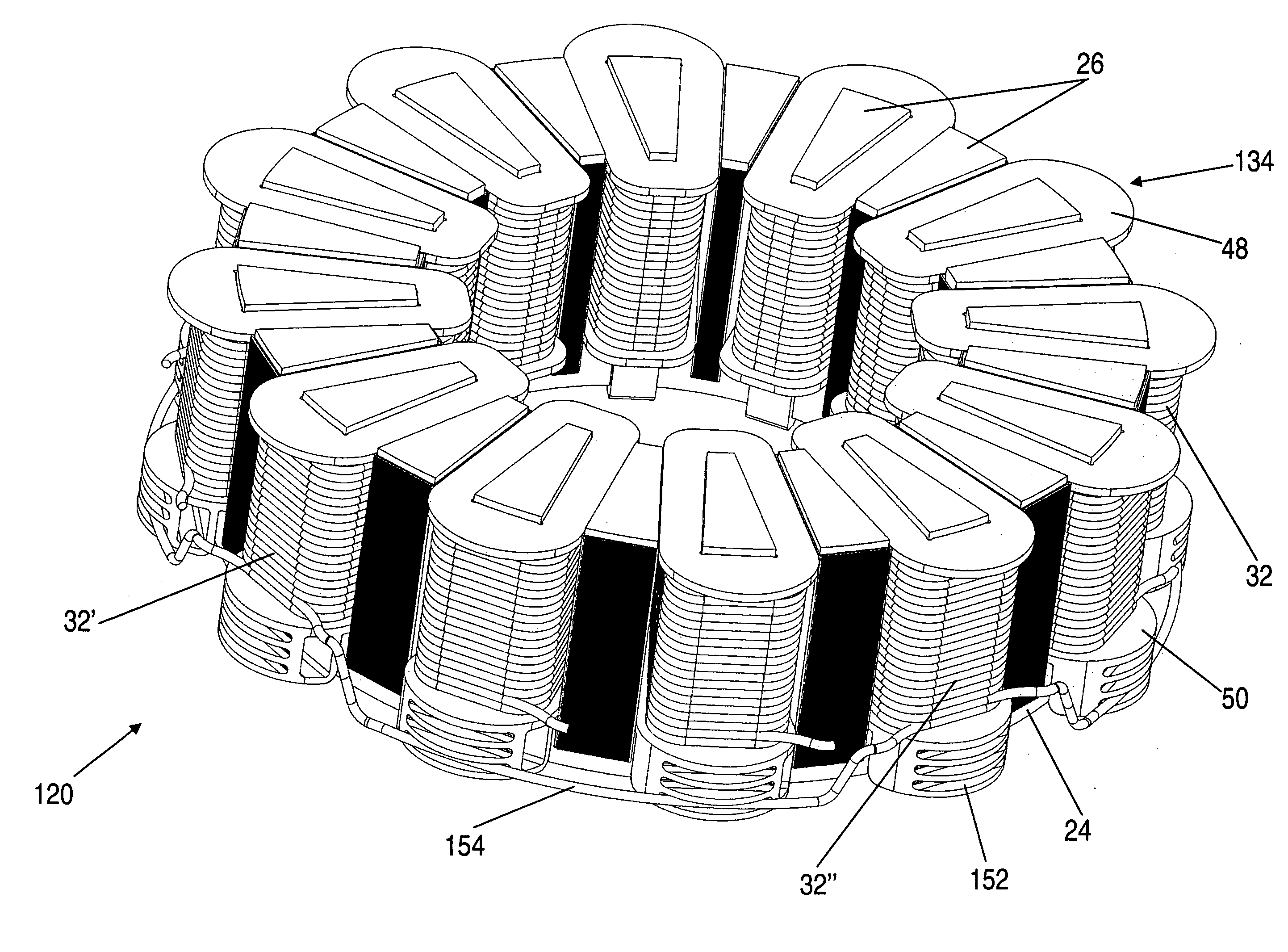
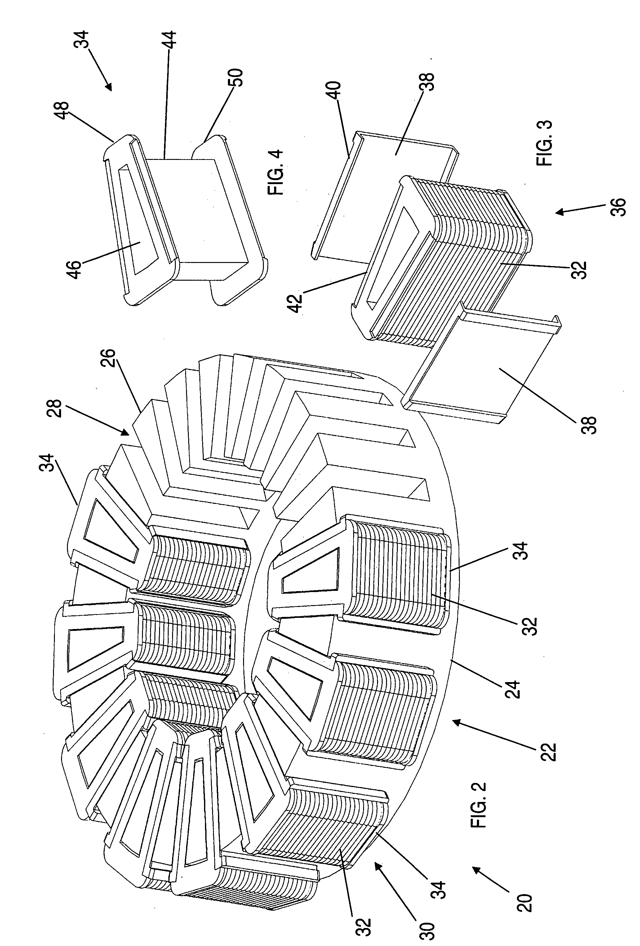
[0042]Referring to the drawings, FIG. 2 shows a partly assembled stator for an axial flux motor in accordance with a preferred embodiment of the present invention. The Stator 20 includes a stator core 22 having a back plane 24 and a plurality of teeth 26 extending from the back plane 24. In use, the back plane 24 is disposed perpendicularly about a rotational axis of the electric motor and the teeth 26 extend axially from the back plane 24 and form winding receiving slots 28 between the teeth 26. The stator 20 also includes an electrical winding 30 made up of a plurality of coils 32 wherein each coil is located about a tooth 26 of the stator core 22. Each of the coils 32 are electrically isolated from their respective stator tooth 26 by means of an insulating former 34. As can be seen in the drawing, the internal shape of the insulating formers 34 closely conforms to the external shape of the stator teeth 26. Although not specifically shown in FIG. 2, each of the coils 32 are interc...


PUM

PropertyMeasurementUnit
shapeaaaaaaaaaa
trapezoidal shapeaaaaaaaaaa
lengthaaaaaaaaaa

Abstract

A stator 20 for an axial flux machine such as a motor or generator. The stator includes a stator core 32 having a back plane 24 which in use is disposed perpendicularly about a rotational axis of the machine. A plurality of teeth 26 extend axially from the back plane so as to form winding receiving slots 28 between adjacent teeth. The stator also includes an electrical winding 30 including a plurality of coils 32, each coil being located about a tooth of the stator core and being electrically isolated from the stator tooth by means of an insulating former 34 having a shape which closely conforms to the shape of the stator tooth. The coils 32 are interconnected to form the winding 30. A method of constructing a stator is also disclosed.

Description

FIELD OF THE INVENTION[0001]The present invention relates generally to electrical machines such as electric motors and generators. In particular, the invention concerns an insulation arrangement for an electrical winding in an axial flux machine with a slotted core. It will be convenient to describe the invention in relation to axial flux motors, as this would be the most common application for the insulation arrangement, but it should be understood that the invention is equally applicable to axial flux generators.BACKGROUND OF THE INVENTION[0002]A motor stator typically includes a laminated electrical steel structure with slots to allow the insertion of conductive windings, typically made from enamelled copper wire. As the stator steel is quite conductive itself, an insulating material is typically added as a lining to the stator slots to prevent electrical current flowing between the copper winding and the steel stator. The material might typically be a sheet of polyester film, su...

Claims


Application Information

Patent Timeline
Patent Type & Authority Applications(United States)
IPC IPC(8): H02K3/34H02K15/02H02K3/38
CPCH02K1/146H02K3/522Y10T29/49009H02K2203/12H02K2203/06H02K3/345H02K15/024
Inventor LANGFORD, CHARLES RICHARDCAMILLERI, STEVEN PETERROHOZA, RAFAL PAWEL
Owner REGAL BELOIT AUSTRALIA PTY LTD
Why Eureka
Try Eureka