Non-Planar Composite Structural Panel

a composite structural panel and non-planar technology, applied in the field of modules, can solve the problems of weak joints, weakened joints, and insufficient waterproofness or airtightness of the foregoing known joining method, so as to improve optics and reflectivity, increase load strength, and improve the effect of resistance to wind loads

Inactive Publication Date: 2011-09-15
CSP SYST INC (US)
View PDF35 Cites 43 Cited by
  • Summary
  • Abstract
  • Description
  • Claims
  • Application Information

AI Technical Summary

Benefits of technology

[0018]Implementations of the present invention provide one or more of the following advantages: increased load strength, increased resistance to wind loads; improved optics and reflectivity, shatter resistance, use of thinner third materials including thinner reflective materials, safer handling and transport of reflective surfaces; and increased life-cycle performance.

Problems solved by technology

These types of joints, however, may be weak.
The panels and / or joints between adjacent panels may lack sufficient strength to resist axial, torsional, or shear loads imposed by the dead weight of the structure, impact forces, or wind loadings.
The foregoing known joining methods often are not sufficiently waterproof or airtight, thereby allowing air and water to infiltrate through the joint and into the panel and / or building formed by the panels without an adequate means of intercepting, directing, or stopping the through-flow of these elements.
Water infiltration may result in structural damage to the panel or reduce its thermal efficiency by wetting the insulating material.
Air infiltration or exfiltration, depending on whether ambient air pressure is greater inside or outside of the structure, results in heat loss and energy inefficiency that translates into higher utility costs for heating and air conditioning.
In inclement weather situations, ambient pressure differentials between the exterior or interior of a structure may cause panels to bow and joints to partially or completely open and fail.
Existing panel fabrication methods are also often complicated and time-consuming, thereby resulting in higher manufacturing and final product costs.

Method used


Image

  • Non-Planar Composite Structural Panel
  • Non-Planar Composite Structural Panel
  • Non-Planar Composite Structural Panel

Examples


example

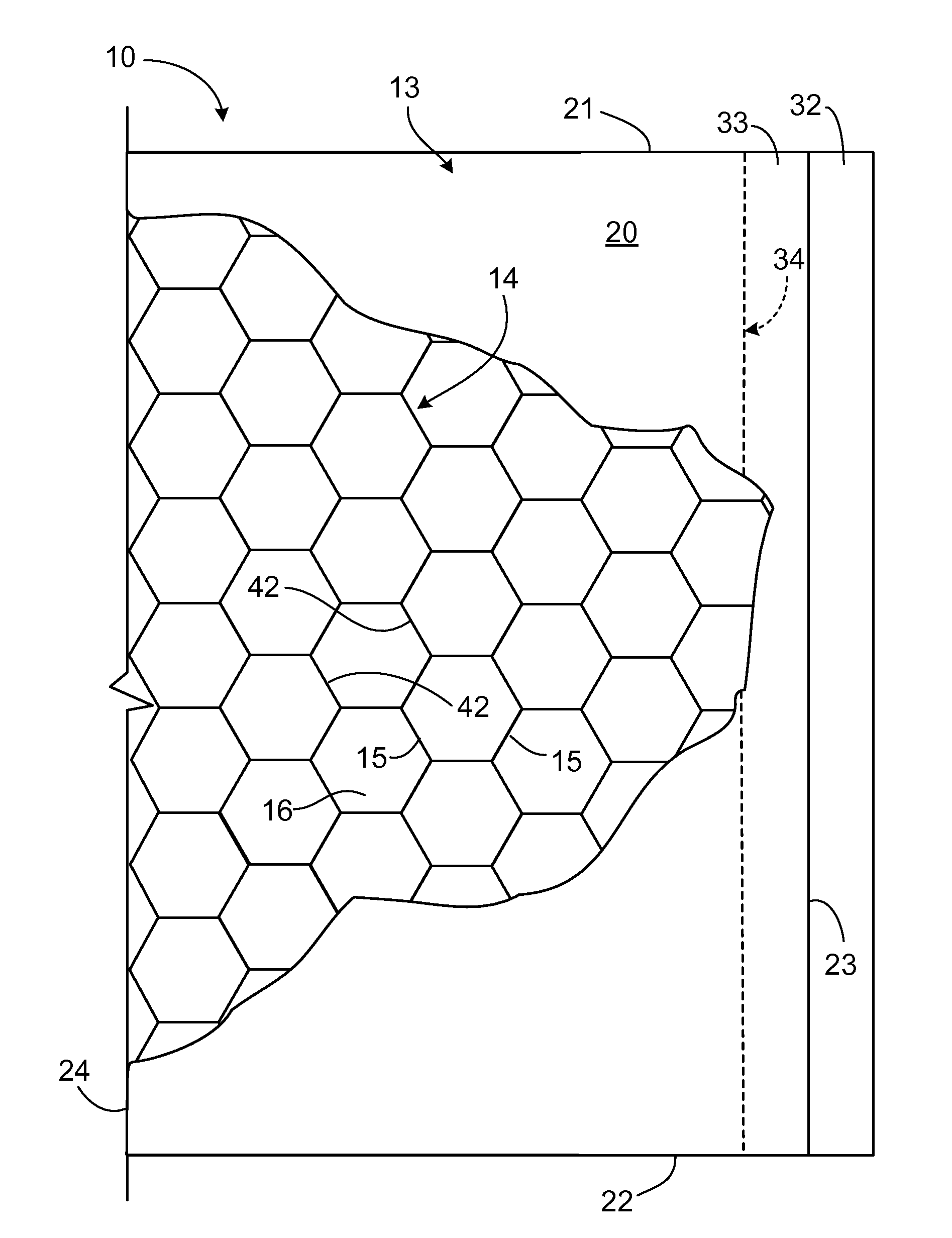
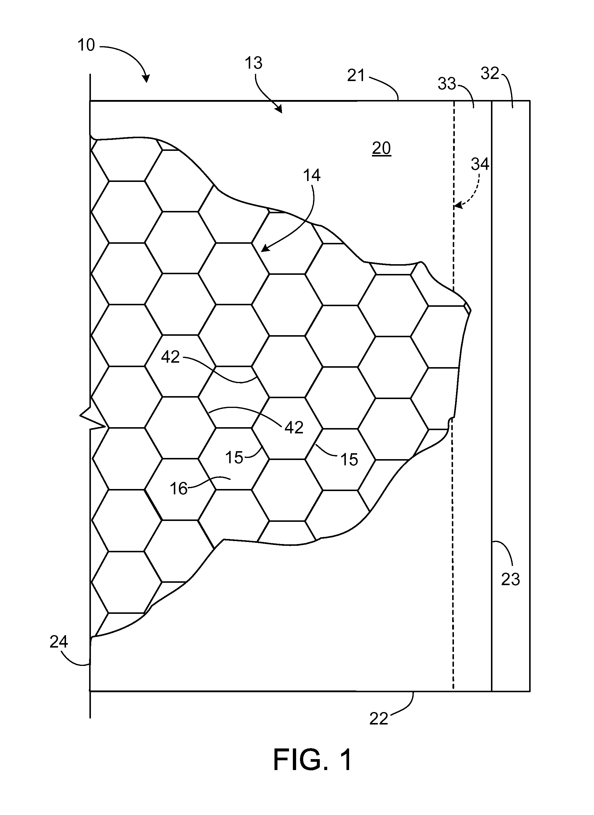
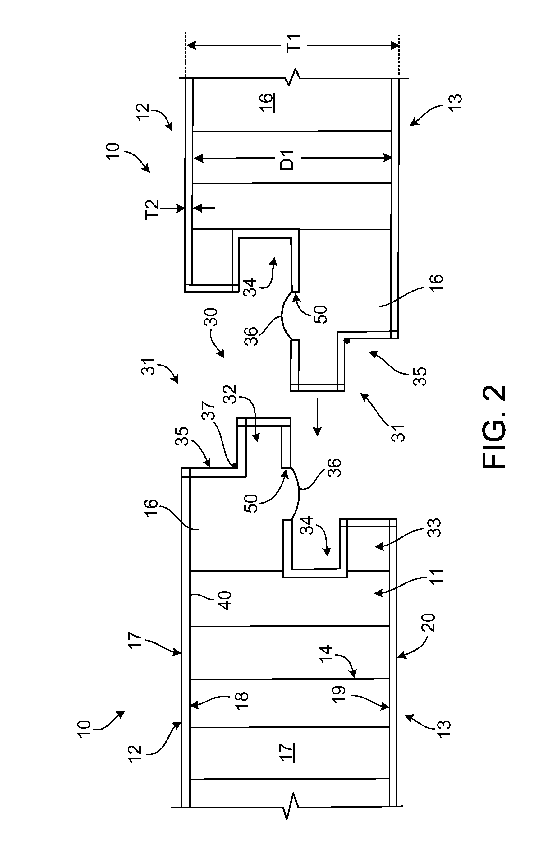
[0070]A non-planar, concave composite solar panel comprises a concave composite solar panel backing and a form fitting mirror on the concave surface of the solar panel backing. The composite solar panel is fabricated by forming an inner and outer skin of 26 ga (0.0179″) G90 galvanized steel into lid like structures. The inner and outer skins have a planar surface having dimensions of approximately 65″×67″. Side walls are formed on the edges of the skin's planar surface. The side walls are formed by folding first side tabs having dimensions of approximately 0.31″×65″ orthogonally from the skin's planar surface. Second side tabs having dimensions of approximately 0.31″×67″ are also folded orthogonally from the skins planar surface and in the same direction as the first side tabs. Two or more of the side tabs forming the side walls are notched with grooves spaced no closer than 1.0″ apart and no further than 6.0″ apart. The exact placement of the notches is dependent on the desired cur...


PUM

PropertyMeasurementUnit
thicknessaaaaaaaaaa
thicknessaaaaaaaaaa
temperatureaaaaaaaaaa

Abstract

An improved non-planar composite structural panel and method of fabrication are provided. Embodiments of the non-planar composite panel comprise: a first sheet including a first outer surface and a first inner surface; a second sheet spaced apart from the first sheet and including a second outer surface and a second inner surface; a stiffening core element disposed between the first and second sheets and defining a plurality of cells; a rigid foam reinforcing material disposed in the cells; and a mirrored third sheet adhered to the first outer surface of the first concave sheet.

Description

CROSS-REFERENCE TO RELATED APPLICATIONS[0001]This application is a continuation-in-part application of and claims priority to U.S. application Ser. No. 11 / 581,598, filed on Jun. 23, 2005, which published as U.S. Patent Application Pub. No. US 2008 / 0086965, on Apr. 17, 2008, the disclosure of which is incorporated herein by reference in its entirety.BACKGROUND OF THE INVENTION[0002]The present invention generally relates to modular structural panels, and more particularly to an improved structural panel, joint, and method of fabricating the same for constructing interconnected panel systems, including curvilinear, arcuate, and convex and concave interconnected panel systems.[0003]Modular building components such as composite structural panels with the ability to be interconnected have been used to construct various types of residential, commercial, and industrial structures. For example, the panels may be interconnected to create walls, floors, ceilings, and partitions of a building ...

Claims


Application Information

Patent Timeline
Patent Type & Authority Applications(United States)
IPC IPC(8): B32B3/02B32B3/12B32B37/00
CPCB32B1/00B32B3/06B32B3/08B32B3/12Y10T428/24661B32B2260/046E04C2/365Y10T428/24149B32B15/04B32B5/02B32B5/18B32B7/12B32B15/043B32B15/08B32B15/12B32B15/14B32B27/00B32B29/00B32B2260/028B32B2262/101B32B2262/106B32B2266/0278B32B2266/06B32B2307/40B32B2307/416B32B2307/50B32B2307/712B32B2307/7246B32B2307/7265B32B2307/732B32B2307/734B32B2419/00B32B2457/12B32B2607/00
Inventor METZ, TIMOTHY W.MCCONNELL, JAMES L.
Owner CSP SYST INC (US)
Why Eureka
Try Eureka