
Magnetic connector

Inactive Publication Date: 2011-09-15
WEST DONALD LEE +1
View PDF5 Cites 3 Cited by
  • Summary
  • Abstract
  • Description
  • Claims
  • Application Information

AI Technical Summary

Benefits of technology

[0004]This invention utilizes the high force of rare-earth magnets to retain dentures. Along with a unique denture structure and installation procedure, precise alignment and fit are easily attained.
[0005]Easy removal and replacement by the wearer allows better hygiene. Because the magnets are retained in the denture they can be easily removed for certain medical procedures such as MRI (Magnetic Resonance Imaging.) Also unique to this invention, when installed, insignificant external magnetic fields occur. All these benefits also apply when used for certain external body prostheses.

Problems solved by technology

Available materials and limited medical knowledge did not allow the implant concept to flourish until more recent times. Even so, certain limitations have kept implantation from being the most used method.
Cost and complexity of implant hardware, along with preparation and installation time, are major impediments.
Most offer fixed angle adapters with complicated means to get “close enough” to the desired angle and elevation.
Imperfect fit of connectors causes wear and loss of connection strength over passage of time.

Method used


Image

  • Magnetic connector
  • Magnetic connector
  • Magnetic connector

Examples


Embodiment Construction

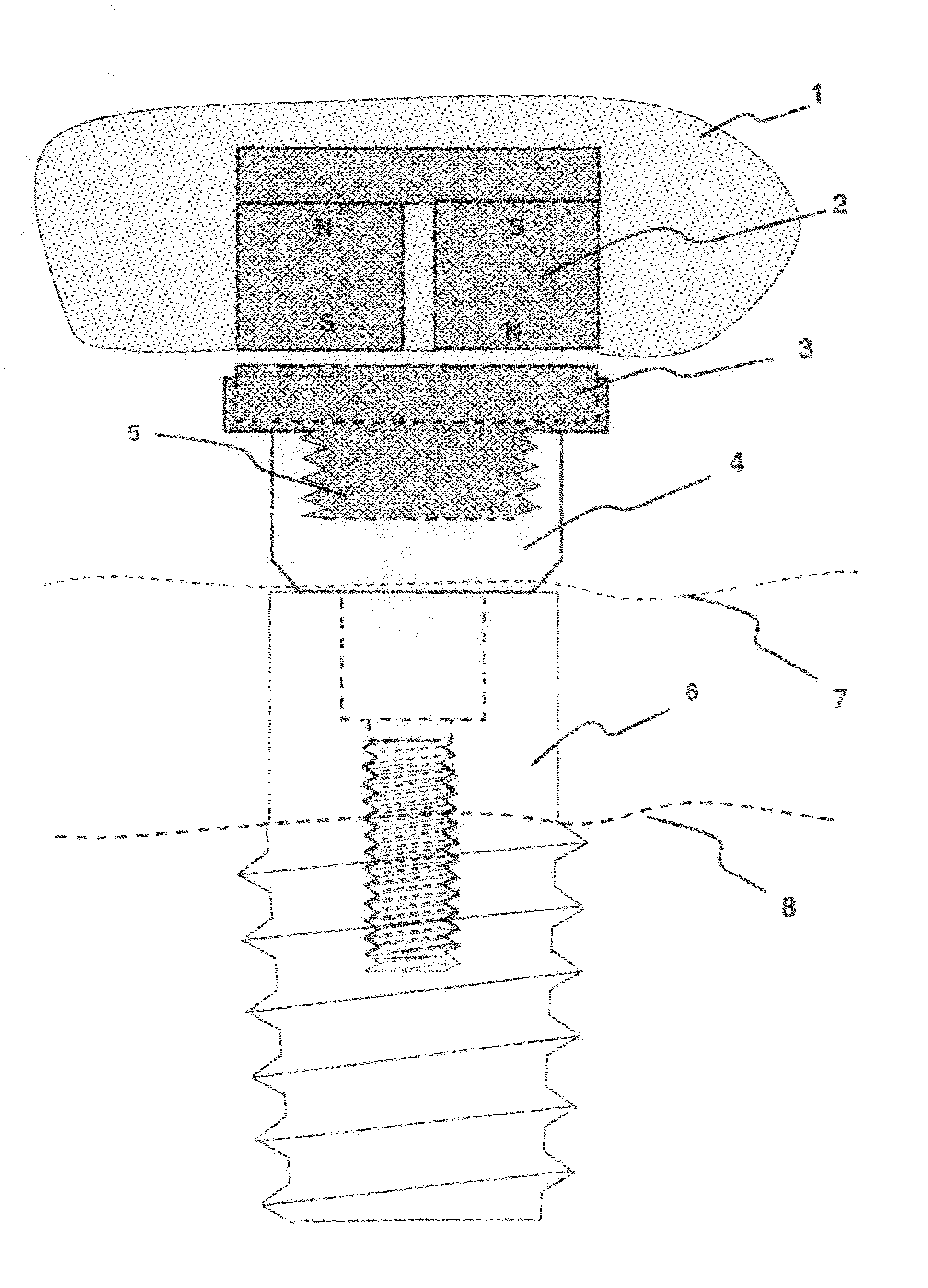
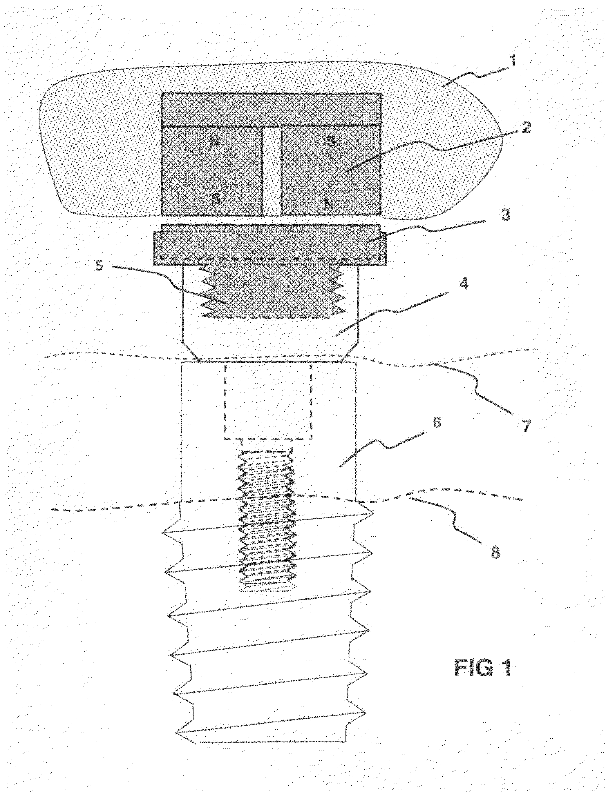
[0010]As indicated by FIG. 1, the primary application of the magnetic coupler is for connecting dentures to dental implant abutments. Implants are screwed into holes that are drilled into jawbone. Irregularity of jawbone structure after removal of the teeth prevents any regular positioning of the implants. Various methods and attachment devices are available to provide uniformity at the connector base such that the connector platform of FIG. 4 will be in a level plane with the other abutment platforms.

[0011]In dental applications, the position and orientation of the platforms will be established and a denture frame will be made for an exact fit. In prostheses applications, meshes and plates of appropriate materials, sizes and shapes can be attached to the magnet assemblies. A prosthesis is cast or formed to retain the magnetic coupler assembly.


PUM


Abstract

This invention claims a magnetic denture or prostheses connection device. Dental implants are an improved method for tooth replacement in that their performance is more similar to natural teeth than are common plate dentures. Unfortunately the implant method is more complex and difficult to build and install. This translates to higher cost to the patient. In the industry there is a variety of mechanisms for connecting a denture to a variety of implant coupling systems. There are both removable and non-removable types. Non-removable dentures are rigidly screwed to the implants or abutments, whereas removable types use snap-together plastic clips. Removable is better from a hygienic perspective.Current coupling and connector devices are seldom a perfect fit even after much care and effort by the installer. This puts high forces on some implants and couplers, and imperfect mating of others. Resulting wear eventually requires repair and / or replacement of connector parts. Also it is important to have forces of chewing distributed as uniformly as possible to the jaw-bone. Concentrated forces can cause stresses at the high force areas and bone degradation of areas where no, or low, force occurs.The high magnetic force of rare earth magnets provide adequate force to retain dentures. While there are many advocates who claim that magnets attached to various body parts do wonderful things, there is no conclusive scientific evidence that verifies these claims. Likewise there is the possibility that high magnetic fields may have harmful effects. For this reason it is desirable that the magnetic fields be contained within any device that will be attached to a place in the body for a long period of time. This invention accomplishes its primary function in a superior fashion while at the same time conserving safety and general health for the applicant. Little, or no, external magnetic fields exist and are totally removed when the denture is removed. These advantages also apply to other applicable prostheses.

Description

[0001]This application claims priority to and benefit of U.S. Provisional Patent Application Ser. No. 61 / 339,894 filed Mar. 11, 2010, entitled “Magnetic Connector.”FIELD OF THE INVENTION[0002]The field of dentistry applies to a range of involvement with oral health from care and maintenance to repair and tooth replacement. This invention relates, primarily, to tooth replacement. Two most used replacement methods of present time are dentures that are retained by suction and bone implant devices to which denture are attached. From earliest history of tooth replacement, implantation was considered and attempted. Available materials and limited medical knowledge did not allow the implant concept to flourish until more recent times. Even so, certain limitations have kept implantation from being the most used method. Cost and complexity of implant hardware, along with preparation and installation time, are major impediments. It remains more an art than a science.[0003]Various suppliers of...

Claims


Application Information

Patent Timeline
IPC IPC(8): A61C13/235
CPCA61C8/0081
Inventor WEST, DONALD LEESPEROW, ARTHUR DEAN
Owner WEST DONALD LEE
Learn More