Modern control concepts for a vehicle internal
combustion engines provide energy-saving or CO2-saving concepts more and more frequently, which may include
voltage-regulated generators, so-called RVC generators, for example. Using these or other technical concepts, in overrun operation with activated overrun cutoff of the engine, i.e., blocked
fuel supply, as much as possible of the
kinetic energy of the vehicle is converted into other
forms of energy, in the example of the RVC generator into electrical energy. In the case of
hybrid vehicles, vehicle batteries can be charged using special generators.
In all of these concepts it is fundamentally not required or even explicitly undesirable for the engine to apply a high braking force in overrun operation if the overrun cutoff is activated, since the
kinetic energy of the vehicle is to be used in other ways as much as possible.
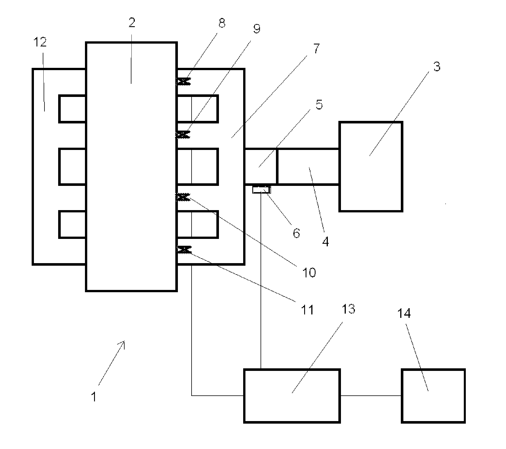
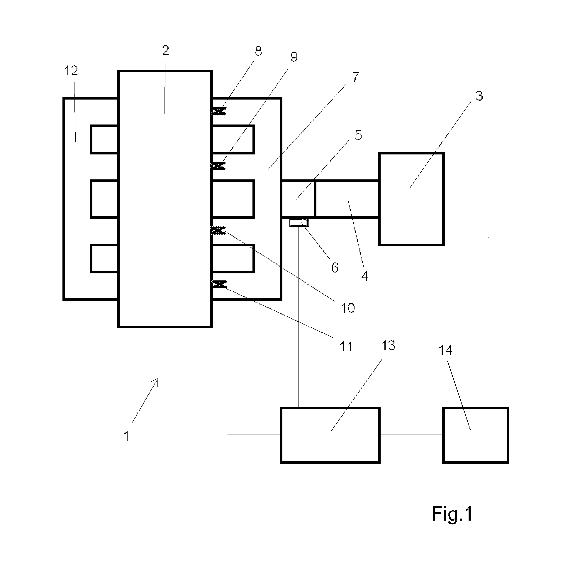
The throttle valve controller according to an embodiment of the invention begins here. It controls the throttle valve in this operating state of the engine in such a way that it is not extensively closed, which results in a relatively high deceleration action of the internal
combustion engine, but rather opens the throttle valve. This is performed when the overrun cutoff of the internal
combustion engine is activated and the gas pedal position is located in a range from unchanged position up to the
rest position of the gas pedal or if the gas pedal is moved in this range, which is fed back to the throttle valve controller in one aspect of the invention using recognition means, in particular a
potentiometer.
Throttle valve controllers are typically designed in such a way that the positioning of the throttle valve is performed according to a gas pedal provided for controlling the engine as a function of its position. Thus, for example, this means that when the gas pedal is returned into its
rest position during driving operation and the overrun cutoff is activated by the engine controller, the throttle valve is moved into an essentially
closed state. This results in maximum deceleration action of the internal combustion engine in overrun operation when the gas pedal is actuated hardly or not at all. This mode of operation of the throttle valve controller was heretofore typically desirable, since the engine is to have maximum
brake action when the “gas” is taken away, i.e., when the gas pedal is not actuated, and the overrun cutoff responds.
The deceleration action of the internal combustion engine is therefore reduced in this operating state, so that the
kinetic energy of the vehicle is
usable for other purposes, for example, to generate electrical energy using other means provided in the vehicle.
This can advantageously go far enough, as provided according to one design of the invention, that the throttle valve is opened so far in the described operating state that it essentially does not throttle the gas
stream flowing through it. In general, this means complete or nearly complete opening. Since the engine controller takes over essential aspects of the
electronic controller of the internal combustion engine, in particular the overrun cutoff, in any case, it can advantageously also be used as the throttle valve controller according to the invention, as is provided according to one embodiment of the invention, so that no separate hardware is to be provided for the throttle valve controller.
Modern control concepts for a vehicle internal combustion engines provide energy-saving or CO2-saving concepts more and more frequently, which may include
voltage-regulated generators, so-called RVC generators, for example. Using these or other technical concepts, in overrun operation with activated overrun cutoff of the engine, i.e., blocked fuel supply, as much as possible of the kinetic energy of the vehicle is converted into other
forms of energy, in the example of the RVC generator into electrical energy. In the case of
hybrid vehicles, vehicle batteries can be charged using special generators.
A throttle valve controller is provided that is implemented, in the case of activated overrun cutoff and unchanged or reducing gas pedal position, to bring the throttle valve using the positioning motor into a position in which the throttle valve throttles the gas
stream flowing through it less than would be the case if the overrun cutoff were not activated in the respective gas pedal position.
Finally, a storage medium is provided in accordance with an embodiment, which is coded using a
machine-readable
program code, the
program code containing control commands for the controller of a computer for performing a method for controlling a throttle valve of an internal combustion engine, having the following steps: Performing an overrun cutoff of the fuel supply of the engine using an electronic engine controller, displacing the throttle valve using an
actuator as a function of a gas pedal position. If overrun cutoff is performed and the position of a gas pedal is unchanged or reducing, the throttle valve is brought via the displacement of the throttle valve controller by the
actuator into a position in which the throttle valve throttles the gas stream flowing through it less than if the overrun cutoff were not performed in the respective gas pedal position.

