Methods and Systems for Parameter-Sensitive and Orthogonal Gauge Design for Lithography Calibration

a lithography calibration and parameter-sensitive technology, applied in the field of design of gauge patterns, can solve the problems of difficult to reproduce a pattern on the wafer, the application of opc is generally not an exact science, and the enormous cost of making high-end mask sets, so as to achieve the effect of maximizing the pattern coverage for model calibration

Inactive Publication Date: 2011-09-15
ASML NETHERLANDS BV
View PDF7 Cites 27 Cited by
  • Summary
  • Abstract
  • Description
  • Claims
  • Application Information

AI Technical Summary

Benefits of technology

[0020]The present invention relates to computationally efficient techniques for designing gauge patterns for calibrating a lithographic process model for use in a simulation process. According to some aspects, the present invention relates to methods of designing gauge patterns that are extremely sensitive to parameter variations, and thus robust against random measurement errors in calibration of a lithographic process utilized to image a target design having a plurality of features. In some embodiments, the process includes identifying a most sensitive line width / pitch combination with optimal assist feature placement which leads to most sensitive CD changes against parameter variations. Another process includes designing gauges which have two main features. The difference between the two main features' CDs is extremely sensitive against parameter variation, and thus robust against random measurement error and any measurement error in bias. In yet another process, patterns are designed that lead to most sensitive intensity.
[0021]According to further aspects, the invention includes methods for designing gauges which minimize the above-described degeneracy, and thus maximize pattern coverage for model calibration. More specifically, the present invention relates to methods of designing gauge patterns that achieve complete coverage of parameter variations with minimum number of gauges and corresponding measurements in the calibration of a lithographic process model utilized to simulate imaging of a target design having a plurality of features. According to some aspects, a method according to the invention includes transforming a model parametric space into a new space (based on CD sensitivity or Delta TCCs), then iteratively identifying the direction that is most orthogonal to existing gauges' CD sensitivities in this new space, and determining a most sensitive line width / pitch combination with optimal assist feature placement which leads to most sensitive CD changes along that direction in a model parametric space.

Problems solved by technology

These rules are set by processing and design limitations.
In general, the smaller k1, the more difficult it becomes to reproduce a pattern on the wafer that resembles the shape and dimensions planned by a circuit designer in order to achieve particular electrical functionality and performance.
However, applying OPC is generally not an exact science, but an iterative process that does not always resolve all possible weaknesses on a layout.
This is driven by the enormous cost of making high-end mask sets, which run in the multi-million dollar range, as well as by the impact on turn-around time by reworking or repairing actual masks once they have been manufactured.
Unfortunately, the conventional art does not include a systematic study on how to determine the type or design of gauge patterns to be used for calibration.
For example, there is no theoretical guidance on the choice of pitch and CD for the line-space patterns or the number of gauges.
Such gauge patterns are often incomplete or super-complete or both for calibration.
For example, none of the chosen gauge patterns will effectively discriminate between certain of the model parameters, thus it may be difficult to determine the parameter values due to measurement inaccuracies.
On the other hand, many patterns can yield very similar responses to different parameter variations, thus some of them are redundant and wafer measurements on these redundant patterns waste resources.

Method used


Image

  • Methods and Systems for Parameter-Sensitive and Orthogonal Gauge Design for Lithography Calibration
  • Methods and Systems for Parameter-Sensitive and Orthogonal Gauge Design for Lithography Calibration
  • Methods and Systems for Parameter-Sensitive and Orthogonal Gauge Design for Lithography Calibration

Examples


second embodiment

[0088]A second embodiment to compute AFGM is called multi-kernel approach. In the multi-kernel approach, mask transmittance M(x) is separated into a pre-OPC component (MT), an assisting feature (AF) component (MA) and an OPC corrections component (MC), i.e.:

M(x)=MT(x)+M A(x)+MC(x)

If

Mk(x)=MT(x)+MC(x)

represents the post-OPC layout transmittance, then by applying the inverse Fourier Transform (i.e., space domain representation) of (Eq. 1), the change in aerial image intensity (Delta I) is

ΔI(x)=∫[MK(x1)+MA(x1)][MK*(x2)+MA*(x2)]ΔW(x-x1,x-x2)x1x2=∫[MK(x1)MK*(x2)+MA(x1)MK*(x2)+MK(x1)MA*(x2)+MA(x1)MA*(x2)]ΔW(x-x1,x-x2)x1x2=ΔIK(x)+∫[MA(x1)MK*(x2)+MK(x1)MA*(x2)]ΔW(x-x1,x-x2)x1x2

where ΔW(x,y) is the space domain representation of the Delta TCC and ΔIT(x) is the Delta AI change in aerial image intensity (Delta I) without assisting features. In practice, the inventors note that the following term of the above equation can be ignored:

∫MA(x1)MA*(x2)ΔW(x−x1, x−x2)dx1dx2

Because MA (associated with ...

first embodiment

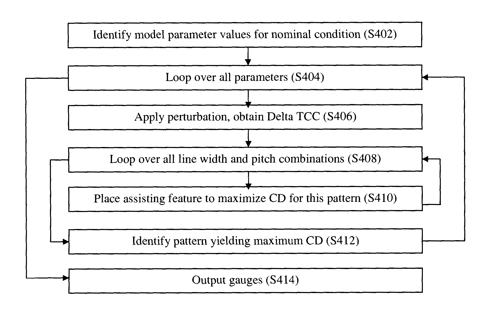
[0131]In a first embodiment, a set of gauges is created to maximize the pair-wise differential CD sensitivity to different parameter variation(s). The resulting gauges are referred to herein as Max-Delta-Parameter-Difference gauges (MDPDG). In particular, between each pair of the parameters, the invention creates pair-wise gauges that maximize the CD sensitivity with respect to the delta-parameter-difference. If there are N parameters, there are CN2=N(N+1) / 2 pairs or N(N+1) gauges. For each pair, this embodiment specifies that there are at least two gauges, represented as (ΔP1, −ΔP2) and (ΔP1, ΔP2), where ΔP1 and ΔP2 denote the perturbed amounts for parameters P1 and P2, respectively. More specifically, for (ΔP1, −ΔP2), this embodiment of the invention designs the gauge that maximizes the CD sensitivity when parameter P1 changes from its nominal value P10 to P10+ΔP1 and P2 changes from its nominal value P20 to P20−ΔP2, simultaneously.

[0132]In this embodiment, the gauge design method...


PUM


Abstract

Methods according to the present invention provide computationally efficient techniques for designing gauge patterns for calibrating a model for use in a simulation process, and which minimize degeneracy between model parameters, and thus maximize pattern coverage for parameter calibration. More specifically, the present invention relates to methods of designing gauge patterns that achieve complete coverage of parameter variations with minimum number of gauges and corresponding measurements in the calibration of a lithographic process utilized to image a target design having a plurality of features. According to some aspects, a method according to the invention includes transforming the space of model parametric space (based on CD sensitivity or Delta TCCs), then iteratively identifying the direction that is most orthogonal to existing gauges' CD sensitivities in this new space, and determining most sensitive line width / pitch combination with optimal assist feature placement which leads to most sensitive CD changes along that direction in model parametric space.

Description

CROSS-REFERENCE TO RELATED APPLICATIONS[0001]The present application claims priority to U.S. Patent Appln. No. 61 / 113,004, filed on Nov. 10, 2008, and U.S. Patent Appln. No. 61 / 140,812, filed Dec. 24, 2008, the full contents of each being incorporated herein by reference.FIELD OF THE INVENTION[0002]The present invention relates generally to designing gauge patterns for calibration associated with a lithography process, and more specifically to computationally efficient methods for designing calibration pattern sets wherein individual patterns have significantly different responses to different parameter variations and are also extremely sensitive to parameter variations, and thus robust against random measurement errors in calibration.BACKGROUND OF THE INVENTION[0003]Lithographic apparatuses are used, for example, in the manufacture of integrated circuits (ICs). In such a case, the mask contains a circuit pattern corresponding to an individual layer of the IC, and this pattern is im...

Claims


Application Information

Patent Timeline
Patent Type & Authority Applications(United States)
IPC IPC(8): G06F17/50
CPCG03F7/70433G03F1/44G03F1/14G06F17/5009G03F7/705G03F1/68G06F30/00G06F30/20G03F1/62G06F17/10
Inventor YE, JUNCAO, YUFENG, HANYINGSHAO, WENJIN
Owner ASML NETHERLANDS BV
Why Eureka
Try Eureka