
Design structure for a phase locked loop with stabilized dynamic response

a dynamic response and design structure technology, applied in the field of design structure, can solve the problems of overdamping of pll, large jitter, and all electronic devices or systems emit unwanted energy, and achieve the effects of improving the performance of conventional feed-forward pll, reducing parameter variation, and optimizing the loop bandwidth

Inactive Publication Date: 2011-06-07
GLOBALFOUNDRIES INC
View PDF7 Cites 1 Cited by
  • Summary
  • Abstract
  • Description
  • Claims
  • Application Information

AI Technical Summary

Benefits of technology

[0016]The mechanisms of the illustrative embodiments provide a hybrid phase locked loop (PLL) circuit for obtaining stabilized dynamic response and independent adjustment of damping factor and loop bandwidth. The hybrid PLL circuit of the illustrative embodiments includes the resistance / capacitance (RC) filter elements of a conventional RC PLL and the feed-forward path from the output of the phase frequency detector to the voltage controlled oscillator (VCO). The hybrid PLL essentially enhances the performance of the conventional feed-forward PLL by providing the RC filter whose components can be weighted to provide a dynamic response that is significantly less sensitive to parameter variation and which allows loop bandwidth optimization without sacrificing damping.

Problems solved by technology

All electronic devices or systems emit some unwanted energy.
If a PLL takes too much time to adjust its response to achieve a desired phase / frequency, the PLL is over-damped.
However, excessive PLL bandwidth will cause larger jitter due to external noise.
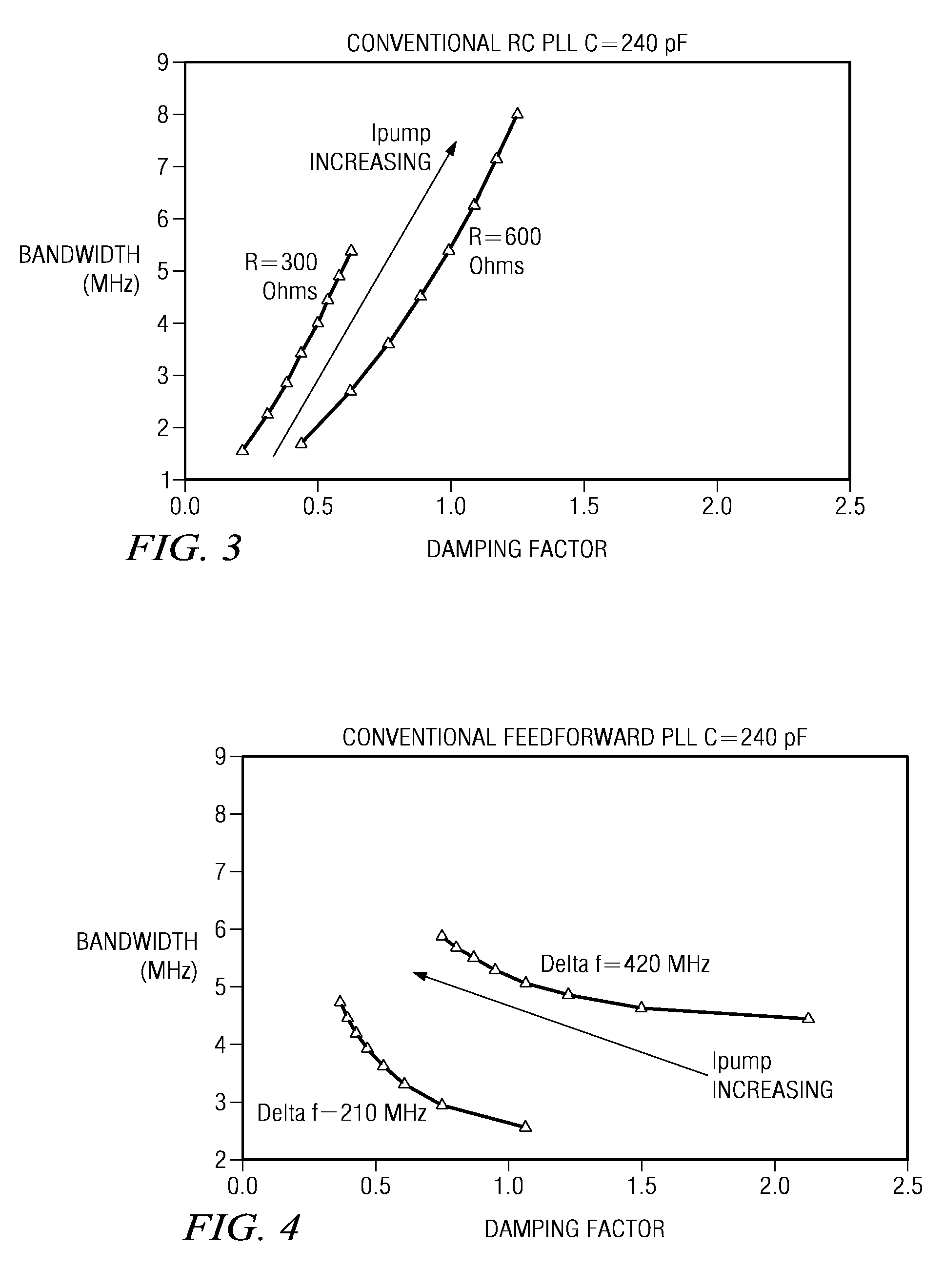
Optimization of the dynamic response of PLLs is often very difficult to achieve because the damping factor and natural frequency / loop bandwidth cannot be set independently for conventional PLL designs.
That is, in conventional PLL designs, any modification to the damping factor of the PLL will also cause a modification in the loop bandwidth.
It is not currently possible to adjust one dynamic response parameter of a PLL independently of the other.

Method used


Image

  • Design structure for a phase locked loop with stabilized dynamic response
  • Design structure for a phase locked loop with stabilized dynamic response
  • Design structure for a phase locked loop with stabilized dynamic response

Examples


Embodiment Construction

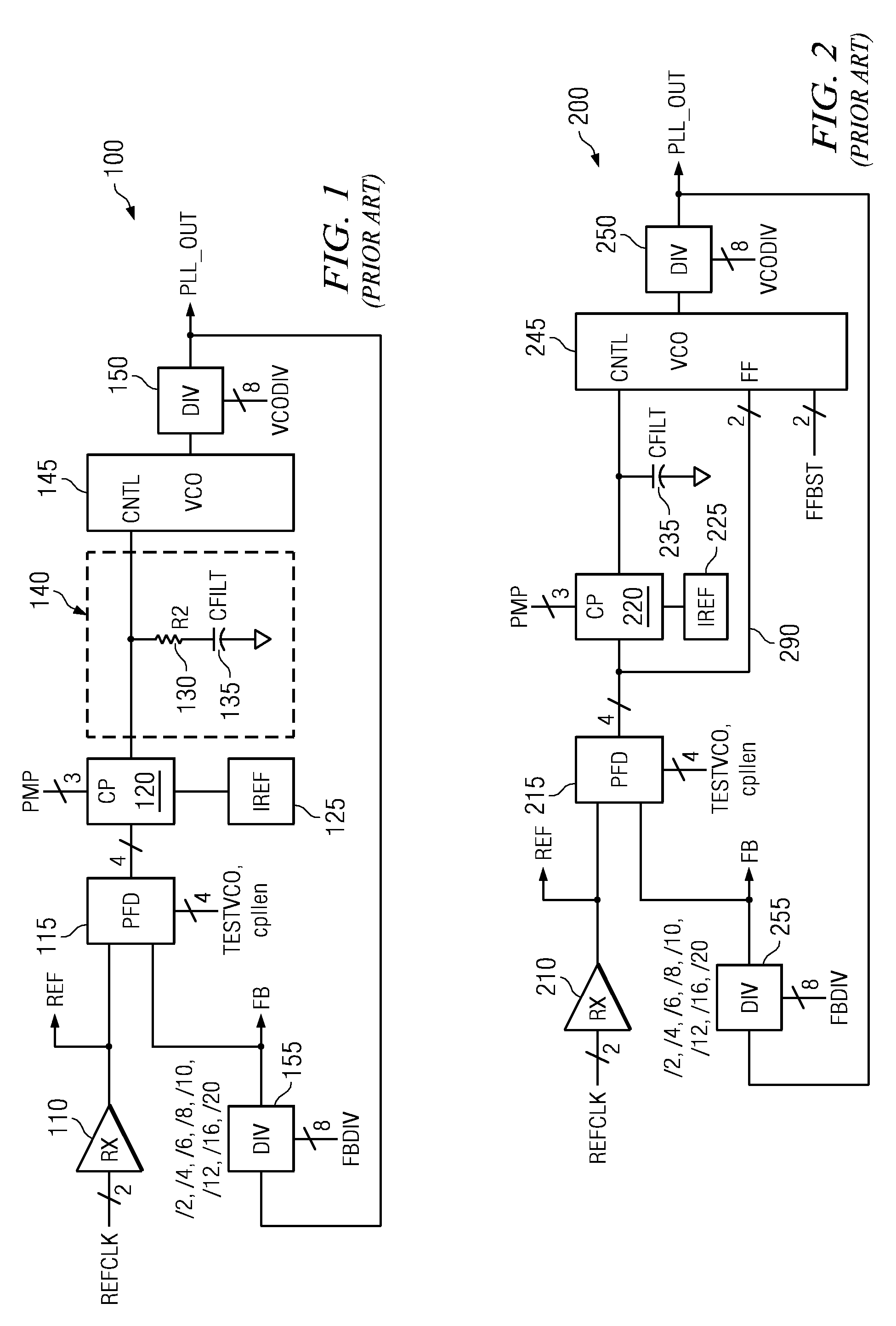
[0040]FIG. 1 is an exemplary block diagram of a conventional RC phase locked loop (PLL) circuit. As shown in FIG. 1, the conventional RC PLL circuit 100 includes a receiver (RX) 110 coupled to a phase frequency detector (PFD) 115 which is in turn coupled to a charge pump (CP) 120. A reference current signal from a reference current circuit (IREF) 125 is provided as an input to the charge pump 120 along with a control input, via a PMP bus for example, specifying the setting of the charge pump 120. The control input, which is set by a configuration register or is hard-wired into the circuit, sets the peak current for the charge pump 120. The charge pump is coupled to a resistor (R2) 130 and capacitor (CFILT) 135 which together constitute a resistance / capacitance (RC) filter 140 (also sometimes referred to as a “loop filter”). The RC filter 140 is coupled to a voltage controlled oscillator (VCO) 145 which in turn is coupled to a first divider 150. A feedback path is provided back to th...


PUM


Abstract

A design structure for a hybrid phase locked loop (PLL) circuit that obtains stabilized dynamic response and independent adjustment of damping factor and loop bandwidth is provided. The hybrid PLL circuit of the illustrative embodiments includes the resistance / capacitance (RC) filter elements of a conventional RC PLL and the feed-forward path from the output of the phase frequency detector to the voltage controlled oscillator (VCO). The hybrid PLL essentially enhances the performance of the conventional feed-forward PLL by providing the RC filter whose components can be weighted to provide a dynamic response that is significantly less sensitive to parameter variation and which allows loop bandwidth optimization without sacrificing damping.

Description

BACKGROUND OF THE INVENTION[0001]1. Field of the Invention[0002]The present application relates generally to a design structure and more specifically, to a design structure for a phase locked loop with stabilized dynamic response.[0003]2. Background of the Invention[0004]A phase locked loop (PLL) is a closed loop feedback control system that generates an output signal in relation to the frequency and phase of an input, or reference, signal. The PLL automatically responds to the frequency and phase of the input signal by raising or lowering the frequency of a controlled oscillator until it is matched to the reference in both frequency and phase.[0005]PLLs are widely used in computing devices, telecommunications systems, radio systems, and other electronic applications where it is desired to stabilize a generated signal or to detect signals in the presence of noise. Since an integrated circuit can hold a complete PLL, the use of PLLs in modern electronic devices is widespread.[0006]PL...

Claims


Application Information

Patent Timeline
Patent Type & Authority Patents(United States)
IPC IPC(8): G06F17/50H03L7/085
CPCH03L7/093H03L7/183H03L7/099H03L2207/04
Inventor BOERSTLER, DAVID W.HAILU, ESKINDERQI, JIEMING
Owner GLOBALFOUNDRIES INC
Learn More