Electric locking and sealing device, case comprising the same, and control system therefor

a technology of sealing device and case, which is applied in the direction of instruments, unauthorized memory use protection, computation using denominational number representation, etc., can solve the problem of hard opening of the case by users, and achieve the effect of preventing power from being stolen, high safety, and preventing reverse connection

Inactive Publication Date: 2011-09-15
HUBEI SHENGJIA ELECTRIC EQUIP +1
View PDF0 Cites 14 Cited by
  • Summary
  • Abstract
  • Description
  • Claims
  • Application Information

AI Technical Summary

Benefits of technology

[0029]Advantages of the invention comprise: it effectively implements sealing of a binding site between two independent connecting parts, and thus preventing external tools from directly contacting with the binding site of the connecting parts; if the invention is applied to an electricity meter case or an electricity meter box, it can effectively prevents power from being stolen by opening the box or the case; it features high safety and makes it possible for a power management department t

Problems solved by technology

However, there is an un-neglectable problem with the conventional methods and devices—they cannot effectively prevent illegal users

Method used


Image

  • Electric locking and sealing device, case comprising the same, and control system therefor
  • Electric locking and sealing device, case comprising the same, and control system therefor
  • Electric locking and sealing device, case comprising the same, and control system therefor

Examples


first embodiment

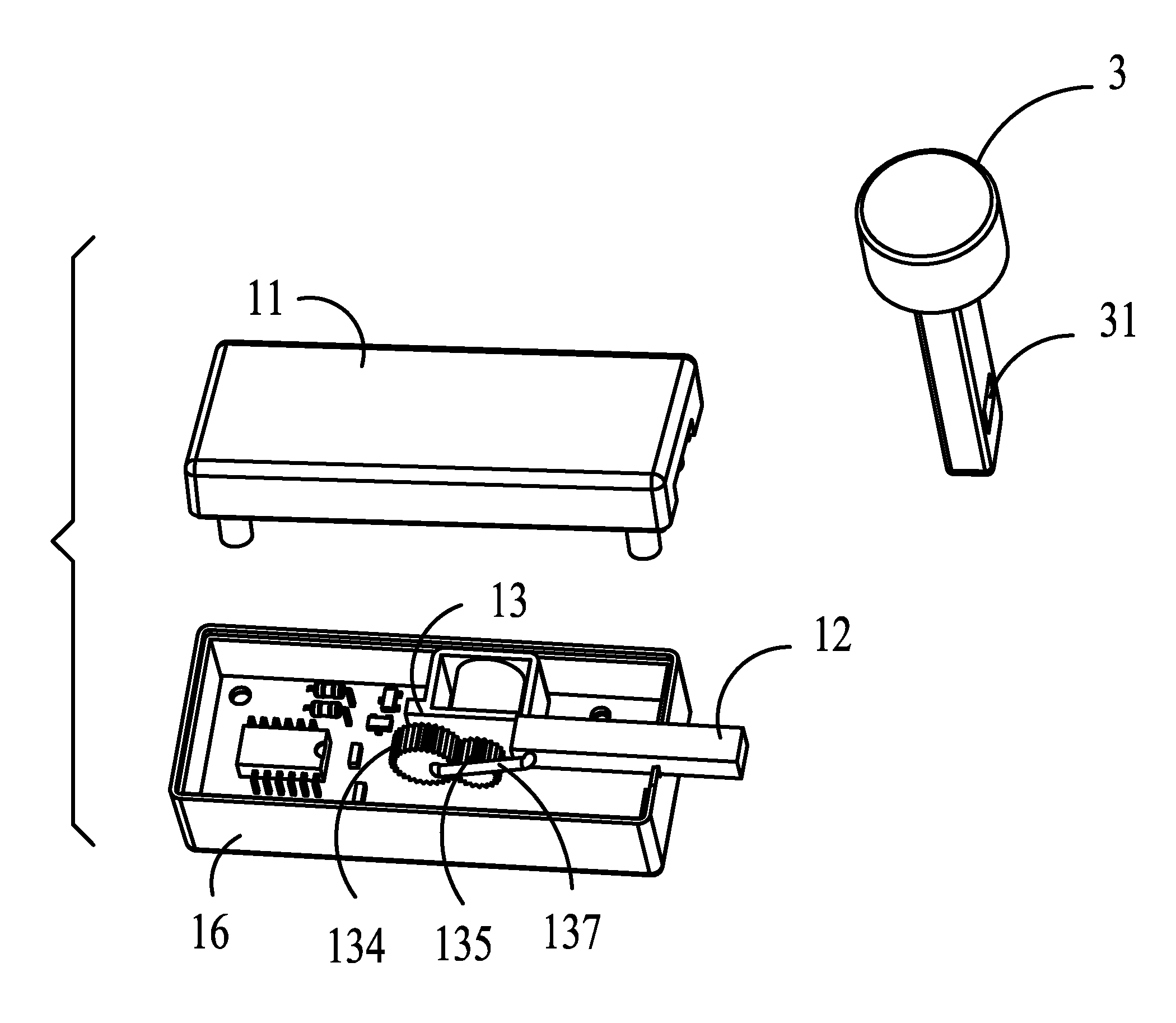
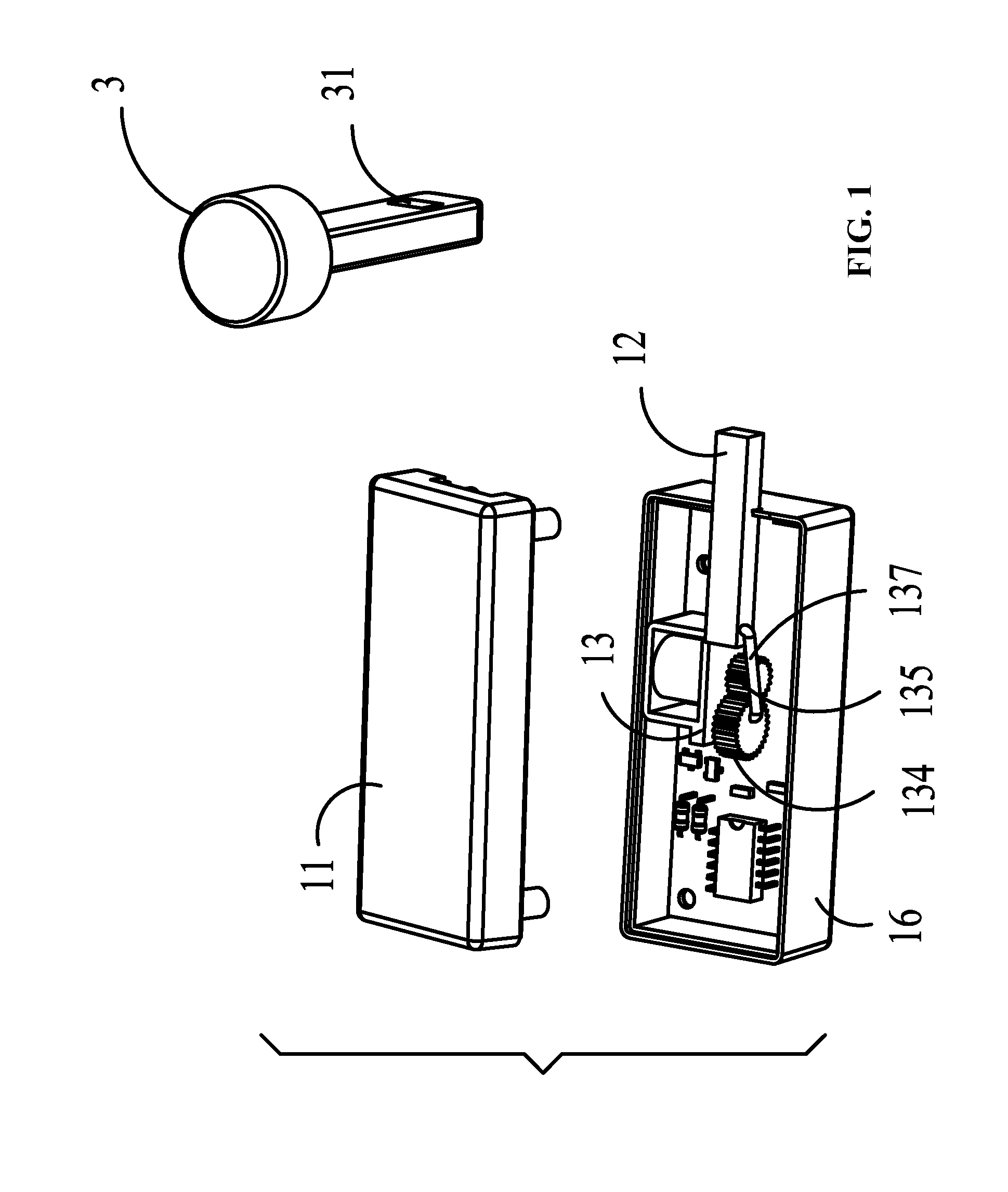
[0055]As shown in FIGS. 10 and 12, the operating unit comprises a power output mechanism having an output end being connected to the lock tongue. The power output mechanism in this embodiment can be the same as that in the first embodiment, or employs an electromagnetic type comprising an electromagnetic operating part, comprising an armature 132, an electromagnetic coil 131, and a load bearing part. One end of the armature 132 is fixedly connected to the lock tongue 12, and integrated in the load bearing part. A reset spring is fit on the armature 132.

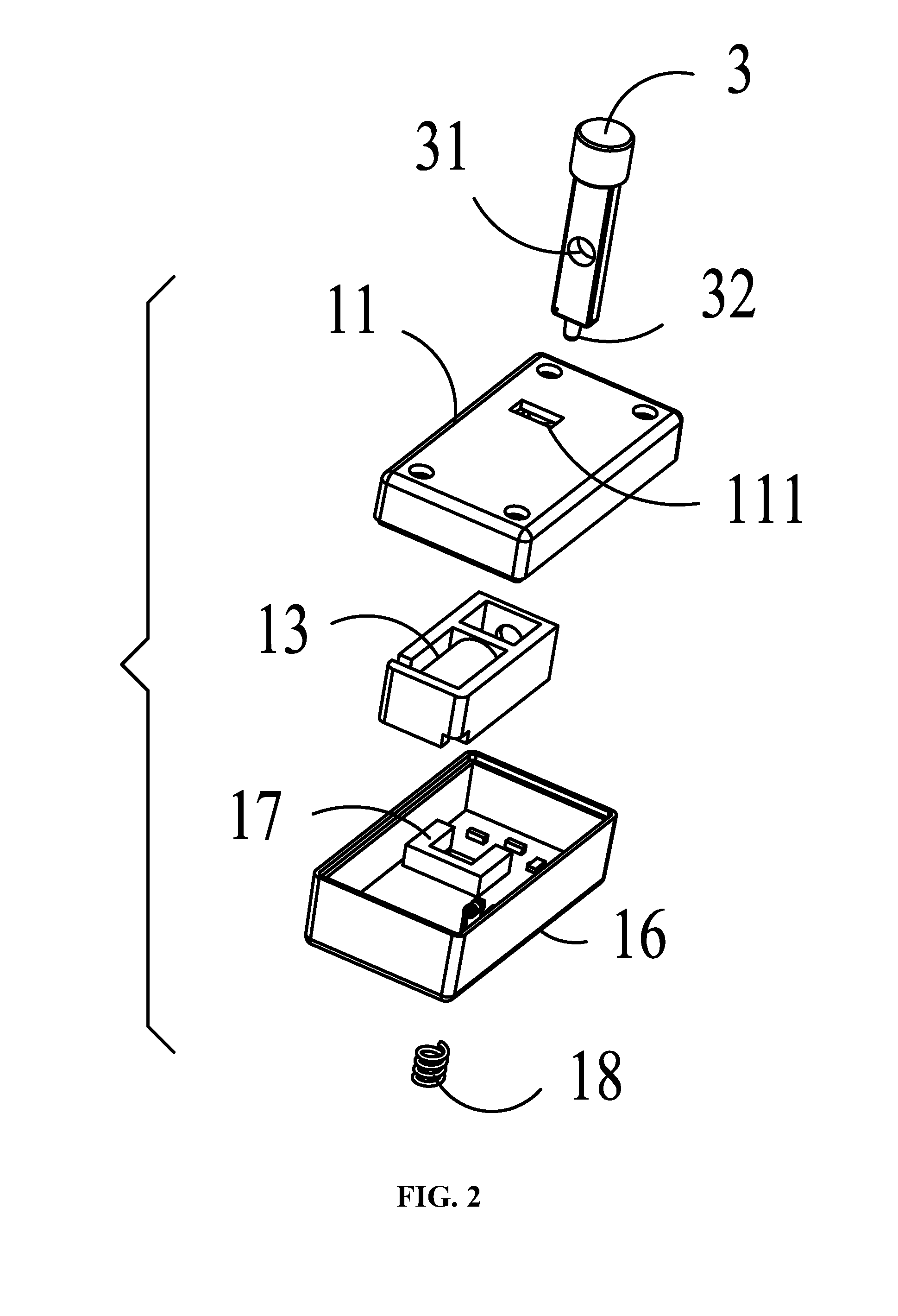
[0056]In addition, a self-test unit is added in comparison with the first embodiment. The self-test unit operates to detect whether the connecting part 3 is received in the opening 111 of the housing, and to trigger the lock tongue 12 to operate. The self-test unit comprises: a U-shaped groove 17, the U-shaped groove 17 comprises a light receiving end, and a light emitting end, a light path being formed therebetween, and a control sig...

third embodiment

[0068]As shown in FIG. 11 and FIG. 12, difference between this embodiment and the third embodiment is that, the electronic locking and sealing device comprises a cap 5 at an installation position of the bottom box 22, and a cap hole 51 is disposed on the cap 5, corresponds to a gap on the box cover 21, and covers the top of the gap of the box cover 21. The connecting part 3 extends from the cap hole 51 of the cap 5, is received in the opening 111 of the upper housing 11 in the box via the gap of the box cover 21, and enters the U-shaped groove 17 of the self-test unit, and thus obstructing a light path. At this time, the main control unit obtains a control signal, the lock tongue 12 extends and is received in the hole 31 of the connecting part. The reset spring 32 at the bottom of the lower housing 16 is compressed, the top of the connecting part 3 is fixed to the cap hole 51 of the cap, and the bottom thereof is received in the housing and blocked by the lock tongue 12, which makes...


PUM


Abstract

An electronic locking and sealing device, including: a housing, a lock tongue, an operating unit, a main control unit, and a connecting part, the operating unit is disposed in the housing and fixedly connected to the lock tongue, and operates to push out or to take back the locking tongue from or in the housing, the main control unit is connected to the operating unit, and operates to receive an external control instruction whereby automatically controlling the operating unit, and the connecting part has a hole disposed at the center thereof and corresponding to the lock tongue.

Description

CROSS-REFERENCE TO RELATED APPLICATIONS[0001]This application is a continuation of International Patent Application No. PCT / CN2009 / 001286 with an international filing date of Nov. 20, 2009, designating the United States, now pending, and further claims priority benefits to Chinese Patent Application No. 200810177929.6 filed on Nov. 20, 2008, and to Chinese Patent Application No. 200910003979.7 filed on Jan. 22, 2009. The contents of all of the aforementioned applications, including any intervening amendments thereto, are incorporated herein by reference.BACKGROUND OF THE INVENTION[0002]1. Field of the Invention[0003]The invention relates to an electronic locking and sealing technique, and more particularly to an electric locking and sealing device, a case comprising the same, and a control system therefor.[0004]2. Description of the Related Art[0005]Nowadays multiple anti-stealing methods and devices are used in electricity meter box, and operate to prevent illegal people from openi...

Claims


Application Information

Patent Timeline
IPC IPC(8): E05B47/00G06F9/30G06F1/26H04L9/00
CPCE05B17/22E05B47/0002E05B47/0004E05B47/0012G01R22/066E05B65/0089E05B2047/0016E05B2047/002E05B47/026Y10T70/7051
Inventor WAN, JIASHENG
Owner HUBEI SHENGJIA ELECTRIC EQUIP
Why Eureka
Try Eureka