Secondary Fuel Premixing Controller for an Air Intake Manifold of a Combustion Engine

a technology of fuel premixing controller and combustion engine, which is applied in the direction of fuel supply apparatus, non-fuel substance addition to fuel, hydrogen, etc., can solve the problems of loss of engine performance, loss of engine power and performance, and other limitations of the related art, so as to reduce the fuel consumption of primary fuel and reduce the consumption of primary fuel. , the effect of reducing the cost of primary fuel

Inactive Publication Date: 2011-09-22
VONGSATEANCHAI SUPOJ +3
View PDF15 Cites 16 Cited by
  • Summary
  • Abstract
  • Description
  • Claims
  • Application Information

AI Technical Summary

Benefits of technology

[0010]This invention is directed to a controller for mixing of a combustible gas or gas mixture including natural gas (CNG), propane, butane, LPG, hydrogen and octane to be used as a secondary fuel mixed fed into the air intake manifold of an internal combustion engine utilized in vehicles such as generators, ships, cranes, airplanes, and helicopters in order to reduce the fuel consumption of the primary fuel which may include octane, diesel, ethanol and...

Problems solved by technology

Single fuel systems which operate on well-known fuels such as gasoline, NGV, LPG, HYDROGEN, biofuels, and diesel fuel are somewhat limited in the efficiency capability that can be achieved operating on such single fuels.
However, common problems in conventional mixers for diesel dual fuel (diesel and LPG fuels...

Method used


Image

  • Secondary Fuel Premixing Controller for an Air Intake Manifold of a Combustion Engine
  • Secondary Fuel Premixing Controller for an Air Intake Manifold of a Combustion Engine
  • Secondary Fuel Premixing Controller for an Air Intake Manifold of a Combustion Engine

Examples


Embodiment Construction
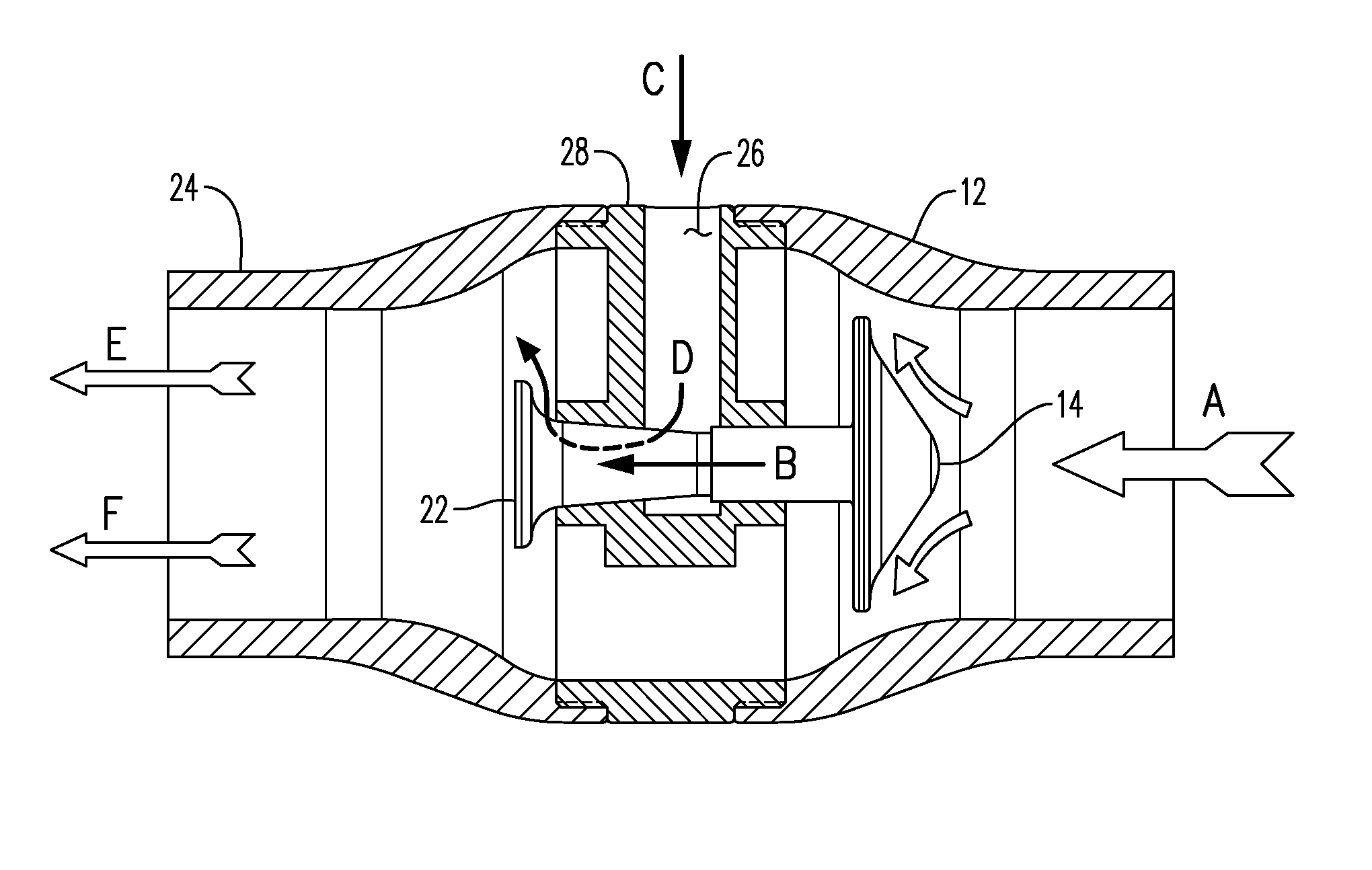
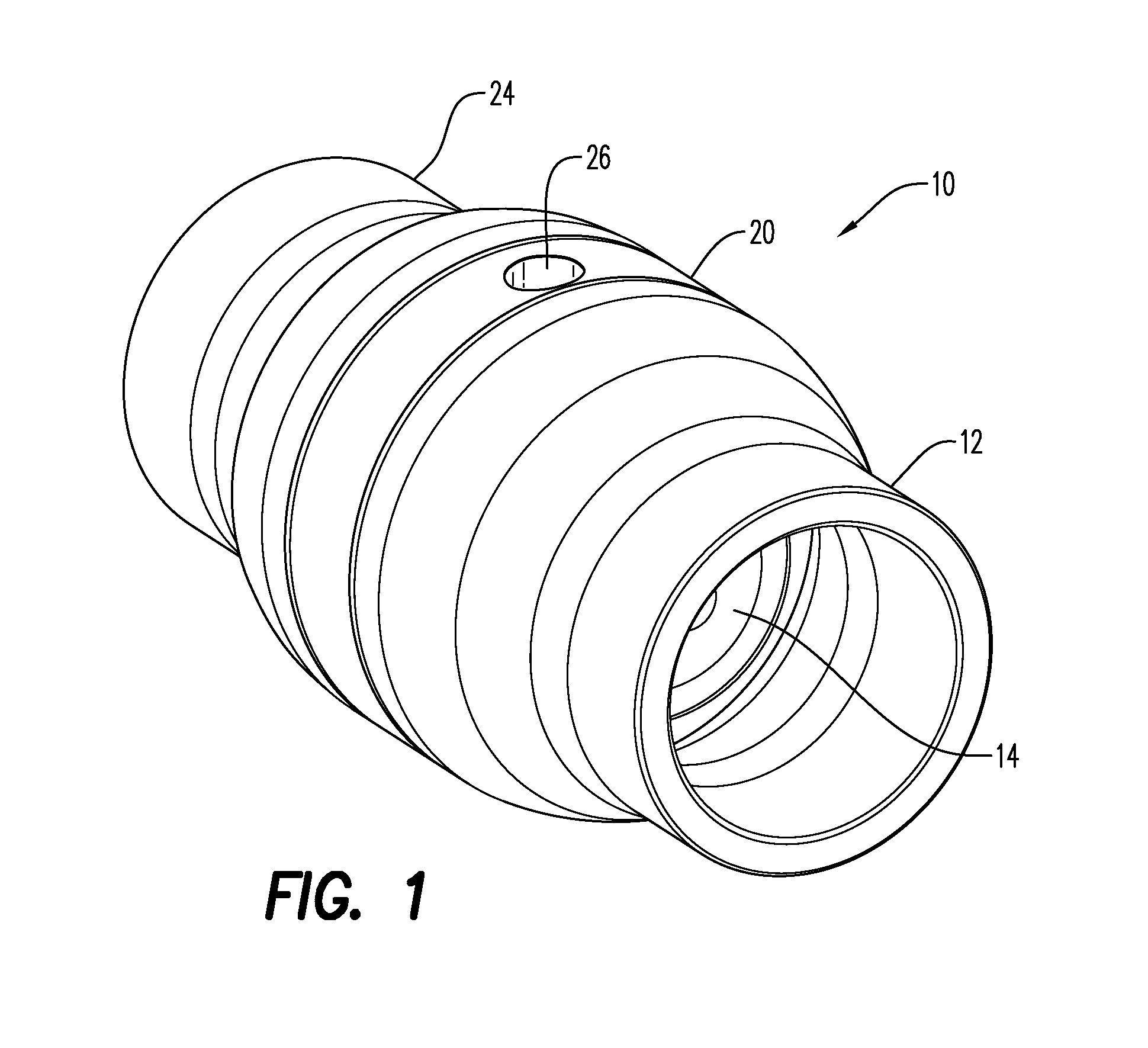
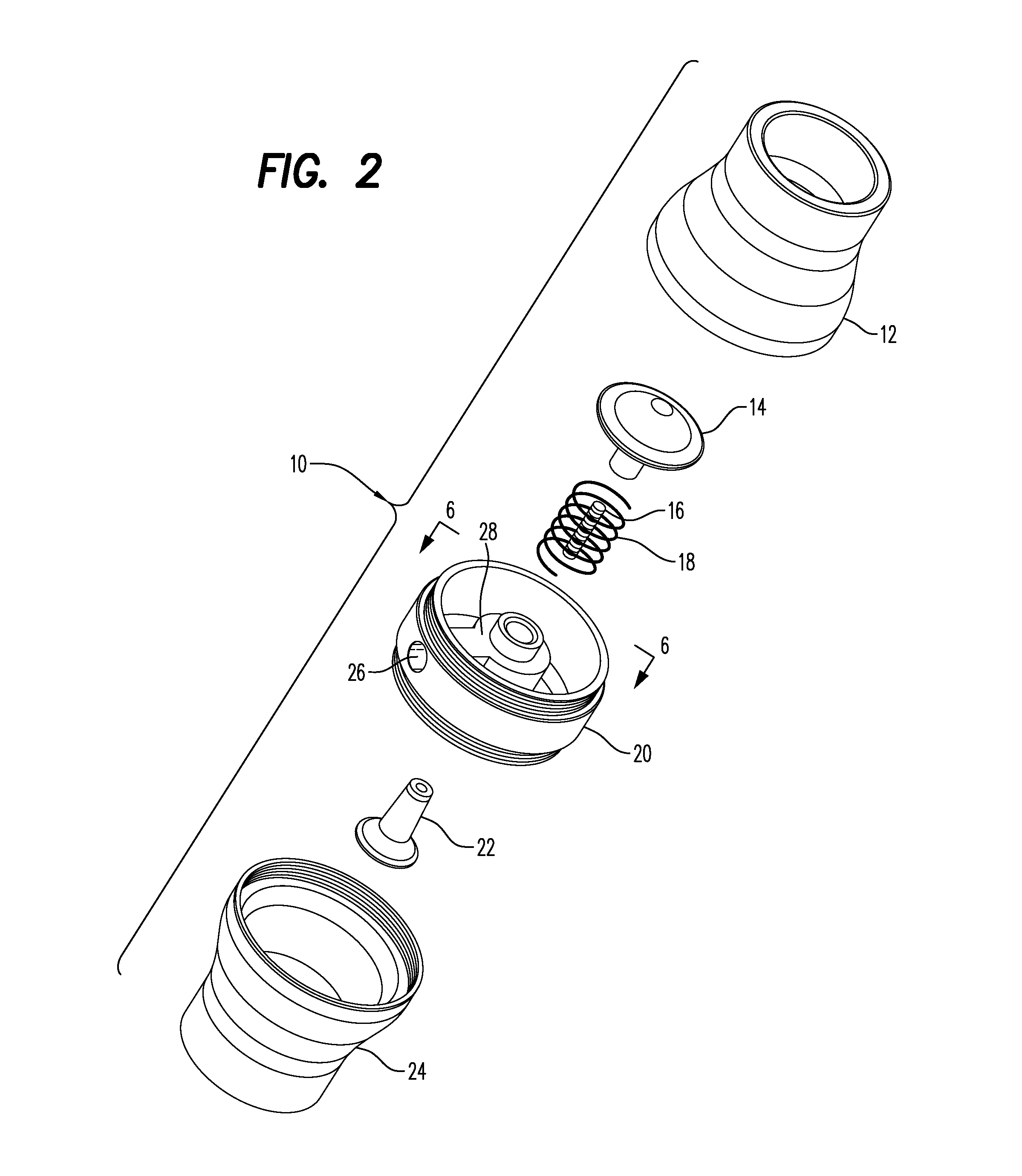
Nomenclature

[0023]10 controller

[0024]12 air inlet

[0025]14 air pressure valve

[0026]16 connector screw

[0027]18 airflow resistance spring

[0028]20 main controller body

[0029]22 secondary fuel / air blender

[0030]24 air / fuel mixing outlet

[0031]26 secondary fuel inlet

[0032]28 secondary fuel manifold

[0033]A inlet airflow

[0034]B valve / blender movement

[0035]C secondary fuel inlet airflow

[0036]D secondary fuel flow through manifold

[0037]E & F blended outlet flow of secondary fuel and air

[0038]Referring now to the drawings, the secondary fuel controller is shown generally at numeral 10 and includes a hollow air inlet 12 threadably engaged with a hollow main controller body 20 at one end thereof, and threadably engaged with an air / fuel mixing outlet 24. The air inlet 12 and the air fuel mixing outlet 24 are preferably formed of molded plastic material, while the main controller body is preferably formed of machined or molded aluminum for added strength. However, alternate materials of a suitable ph...


PUM


Abstract

A secondary fuel premixing controller for introducing a secondary fuel into an air intake manifold of a primary fuel combustion engine. The controller includes a hollow housing having an air inlet, a main controller body, and an air/secondary fuel mixing outlet connected together in central alignment one to another. The air inlet introduces incoming air into the controller while the air/fuel mixing outlet discharges a blended mixture of secondary fuel and air into an air intake manifold of the running engine. The main controller body includes a secondary fuel manifold positioned centrally within an interior of the controller which supports for axial movement an air pressure valve positioned proximate to the air inlet and a secondary fuel/air blender connected thereto. The secondary fuel manifold also has a secondary fuel inlet formed therethrough connectable at an outer end thereof to a source of secondary fuel, an inner end positioned for sealing engagement with the secondary fuel/air blender. The air pressure valve and secondary fuel/air blender are biased to close and seal the inner end of secondary fuel inlet when the engine is stopped and to open the inner end responsive to engine intake air intake through the controller when the engine is running.

Description

CROSS-REFERENCE TO RELATED APPLICATIONS[0001]Not applicableSTATEMENT REGARDING FEDERALLY SPONSORED RESEARCH OR DEVELOPMENT[0002]Not applicableINCORPORATION-BY-REFERENCE OF MATERIAL SUBMITTED ON A COMPACT DISC[0003]Not applicableBACKGROUND OF THE INVENTION[0004]1. Field of the Invention[0005]This invention relates generally to devices and apparatus for improving the fuel efficiency of an internal combustion engine, and more particularly to a secondary fuel controller which selectively introduces alternate fuels such as natural gas (NGV), liquefied petroleum (LPG), and hydrogen (HYDROGEN) into the air intake system of a combustion engine of a vehicle.[0006]2. Description of Related Art[0007]Single fuel systems which operate on well-known fuels such as gasoline, NGV, LPG, HYDROGEN, biofuels, and diesel fuel are somewhat limited in the efficiency capability that can be achieved operating on such single fuels. However, many improvements in the fuel / air intake system for internal combusti...

Claims


Application Information

Patent Timeline
IPC IPC(8): F02M25/07
CPCF02M35/10216Y02T10/36F02M21/04Y02T10/32F02D19/0647F02D19/081F02D19/0644Y02T10/30
Inventor VONGSATEANCHAI, SUPOJRAKDEE, CHOLATHORNVINAISOMPAN, WISOTHSEANGLUM, NITNIPA
Owner VONGSATEANCHAI SUPOJ
Why Eureka
Try Eureka