Rotary wing vehicle

a rotary wing and vehicle technology, applied in the field of vehicles, can solve the problems that the full or partial authority thrust vectoring cannot usually be achieved without significant engineering cost, and achieve the effect of reducing thrust and simplifying and fastening the translation control respons

Inactive Publication Date: 2011-09-22
UNIV OF MANCHESTER
View PDF13 Cites 143 Cited by
  • Summary
  • Abstract
  • Description
  • Claims
  • Application Information

AI Technical Summary

Benefits of technology

[0015]It can be appreciated that decoupling translation and rotational control allows a simpler and faster translation control response to be realised as compared to that achievable by vehicles that do not have thrust and torque vectoring capability. A further advantage of embodiments of the invention is that at least one of independent thrust and torque vectoring coupled with a suitable vehicle frame or body makes vehicle translation along a surface possible, including pressing the vehicle against an inclined surface such as, for example, a wall. The latter has the advantage that hovering with reduced thrust (and hence power consumption) can be realised due to frictional coupling with the surface.
[0016]Embodiments of the present invention enable Rtb to vary independently since a required acceleration vector can be achieved using thrust vectoring, which means that no gimballing is required thereby providing significant advantages to embodiments of the invention.
[0017]Embodiments of the invention are able to provide vehicles with at least one of thrust and torque vectoring concurrently with providing sufficient thrust to accelerate the vehicle with an acceleration magnitude of at least g ms−2, where g is the acceleration due to gravity, such that weight support and maneuvering is possible.

Problems solved by technology

Full or partial authority thrust vectoring cannot usually be achieved without significant engineering cost.

Method used


Image

  • Rotary wing vehicle
  • Rotary wing vehicle
  • Rotary wing vehicle

Examples


Embodiment Construction

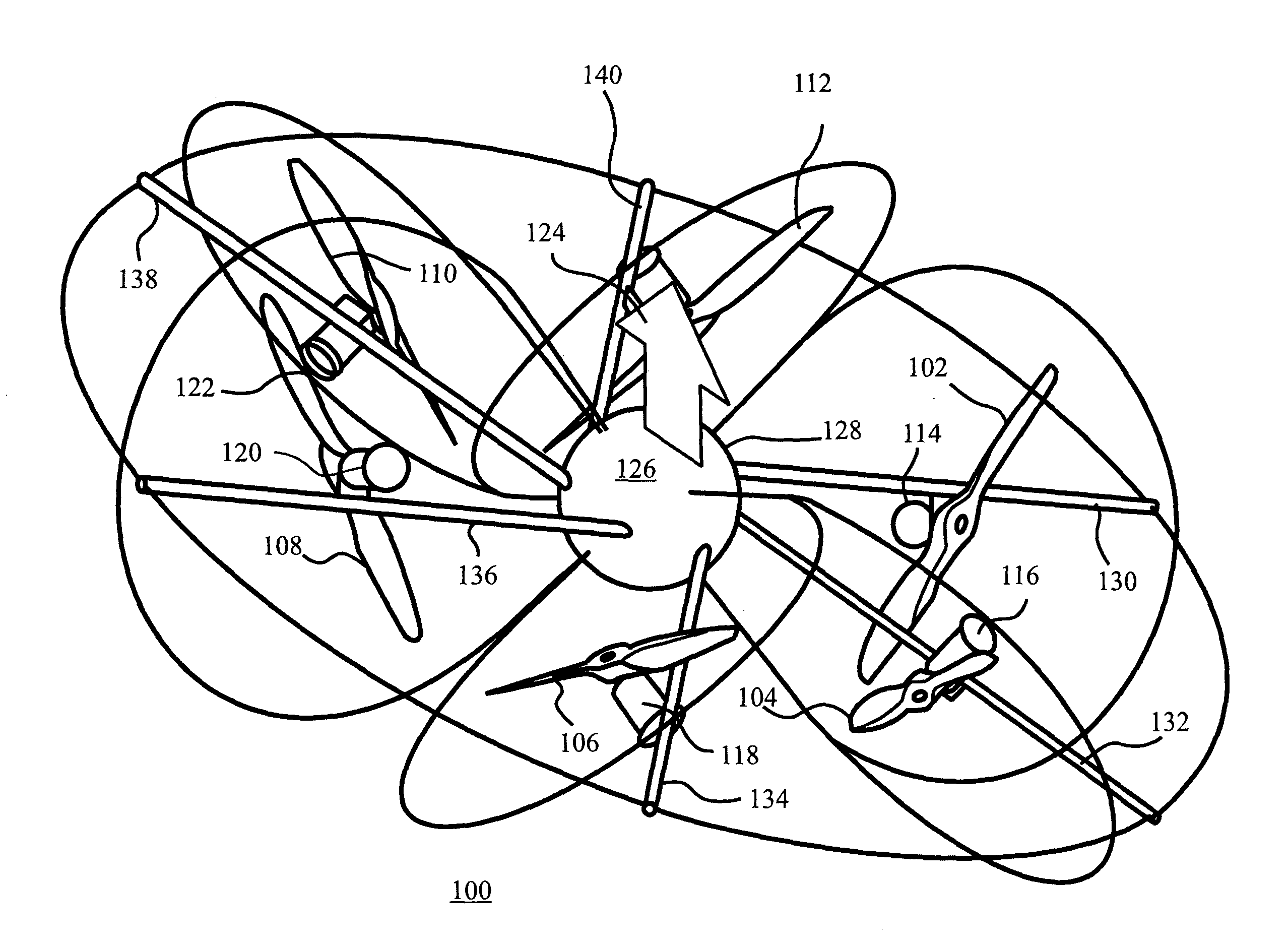
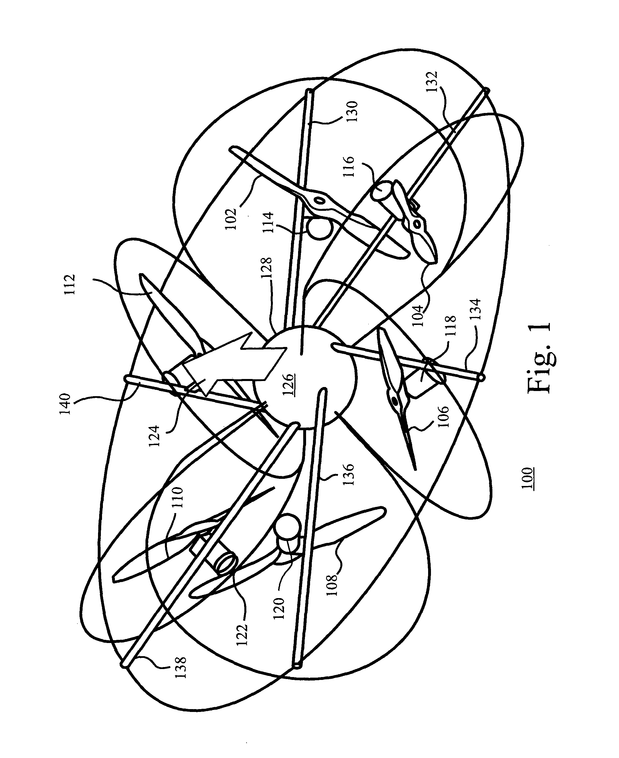
[0049]FIG. 1 shows a rotary wing vehicle 100 according to an embodiment of the invention. The vehicle comprises six rotors 102 to 112. The six rotors 102 to 112 are arranged in pairs in three inclined planes (not shown), referred to as disc planes. For the example shown here, the disc planes are orthogonal to each other, however note that the angle between disc planes may be chosen arbitrarily. The rotors 102 to 112 are driven by respective motors 114 to 124. The rotor-motor combinations have a fixed orientation relative to the body 126, or body axes, of the vehicle 100. Therefore, each rotor 102 to 112 provides a respective thrust vector having a fixed orientation relative to a plane (not shown) of the vehicle that comprises the centres of rotation of the rotors 102 to 112. The plane is known as the Vehicle Reference Plane (VRP), which is shown in FIG. 7. The vehicle body 126 comprises a central hub 128 bearing a number of spokes or struts 130 to 140. The rotor-motor arrangements a...


PUM


Abstract

Embodiments of the invention relate to a vehicle comprising a plurality of inclined rotors that are operable to provide at least one of thrust and torque vectoring according to a desired thrust and/or torque vectors.

Description

FIELD OF THE INVENTION[0001]Embodiments of the invention relate to a vehicle and, more particularly, to a rotary wing vehicle.BACKGROUND TO THE INVENTION[0002]A helicopter generates lift using a rotor system. A rotor system comprises a mast, a hub and rotor blades. The mast is coupled to a transmission and bears the hub at its upper end. The rotor blades are connected to the hub. Helicopters are classified according to how the rotor blades are connected and move relative to the hub. There are three basic classifications for the main rotor system of a helicopter, which are rigid, semi-rigid and fully articulated.[0003]Typically, a helicopter has four flight control inputs, which are the cyclic, the collective, the anti-torque pedals, and the throttle. The cyclic control varies the pitch of the rotor blades cyclically, which tilts the rotor disc formed by the rotor blades in operation in a particular direction resulting in movement of the helicopter in that direction. For example, mov...

Claims


Application Information

Patent Timeline
Patent Type & Authority Applications(United States)
IPC IPC(8): B64C27/08
CPCB64C1/30B64C15/02B64C2201/108B64C39/024B64C2201/027B64C27/08B64U10/13B64U30/20B64C39/003B64C39/005
Inventor CROWTHER, WILLIAMPILMOOR, MATTHEWLANZON, ALEXANDERGEOGHEGAN, PHILIP
Owner UNIV OF MANCHESTER
Why Eureka
Try Eureka