Saturation correction for ion signals in time-of-flight mass spectrometers

a mass spectrometer and time-of-flight technology, applied in mass spectrometers, separation processes, separation of dispersed particles, etc., can solve the problems of limiting the intensity dynamics of individual time-of-flight spectrum to two orders of magnitude, not fully compensating, and exceeding the saturation limit. achieve the effect of increasing the dynamic measurement range of the spectrum acquisition process

Inactive Publication Date: 2011-09-22
BRUKER DALTONIK GMBH
View PDF13 Cites 22 Cited by
  • Summary
  • Abstract
  • Description
  • Claims
  • Application Information

AI Technical Summary

Benefits of technology

[0017]According to still another aspect of the invention, a method is provided to increase a dynamic measurement range of a spectrum acquisition process. Measured values from an analog-to-digital converter (ADC), which are in saturation, may be replaced with correction values. The correction values may be added to provide a sum time-of-flight spectrum. The correction values may be derived from the width of the signals; e.g., from the number of measured values in saturation.

Problems solved by technology

However, this limits the intensity dynamics in an individual time-of-flight spectrum to two orders of magnitude; e.g., from around 2.5 counts to 255 counts.
Due to the ongoing development of ion sources and mass spectrometers, however, the aforesaid saturation limit is being reached and exceeded more and more often.
This is because focusing errors of the mass spectrometers, not fully compensated effects of initial energy distributions of the ions before their acceleration into the flight path, and other influences also play a part.
The aforesaid signal widths of the ion signals may limit the resolution of the time-of-flight mass spectrometers.
The use of multiply bent flight paths with several reflectors to improve resolutions, however, has not proven to be a good solution.
Such conditional additions are not easy to carry out, however, because the complete algorithm runs at four or even eight gigahertz, which is very difficult even when using relatively fast FPGA (field programmable gate arrays) or relatively fast digital signal processors (DSP).
The aforesaid method of increasing the mass resolution and the mass accuracy, however, does not increase the dynamic measurement range.

Method used


Image

  • Saturation correction for ion signals in time-of-flight mass spectrometers
  • Saturation correction for ion signals in time-of-flight mass spectrometers
  • Saturation correction for ion signals in time-of-flight mass spectrometers

Examples


Embodiment Construction

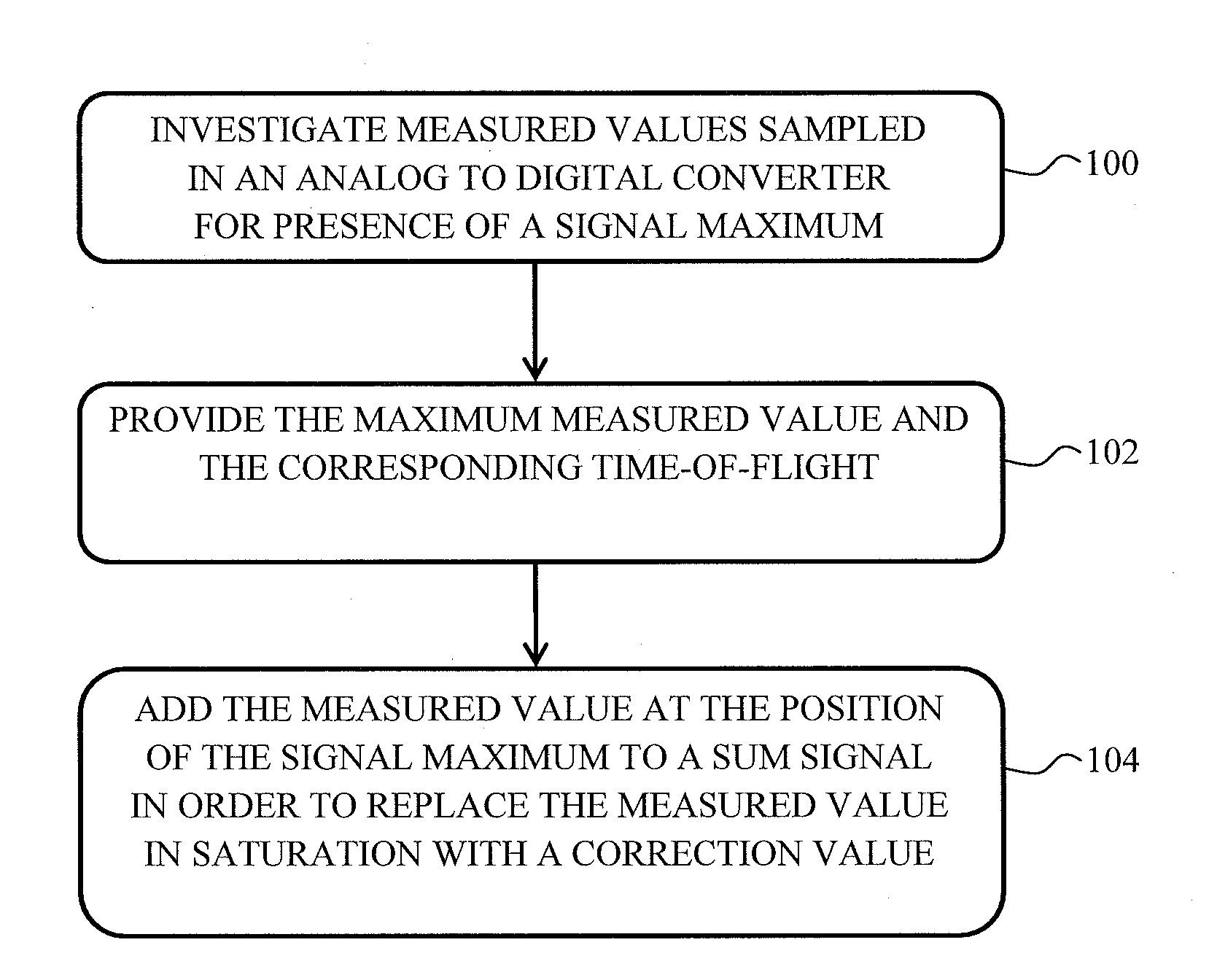
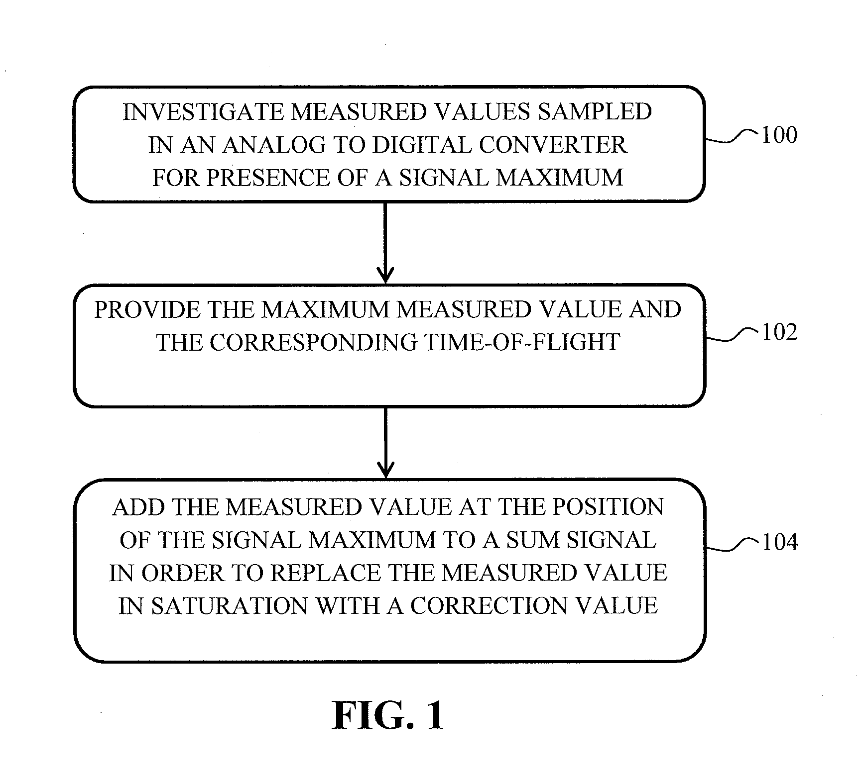
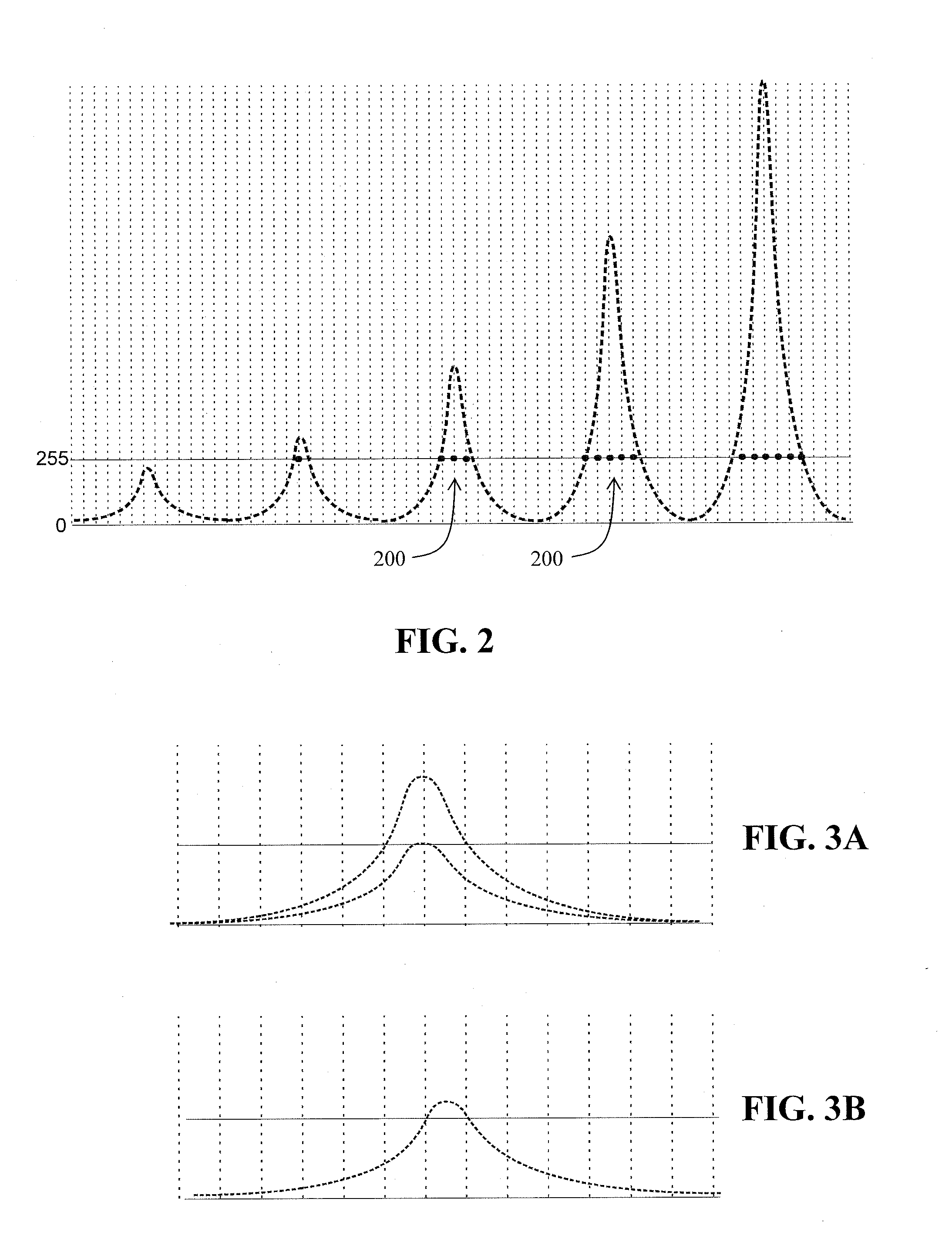
[0025]A method for increasing a dynamic measurement range of a spectrum acquisition of a time-of-flight mass spectrometer is provided. Ion signals that drive an analog-to-digital converter (ADC) into saturation in an individual time-of-flight spectrum are replaced with correction values (also referred to as “corrected values”) where, for example, the saturation values extend over a plurality successive measurements. The correction values may be derived from a width of the ion signals; e.g., from a number of measured values in saturation. Since the signal forms may change as a function of the mass of the ions, the correction values may additionally depend on time-of-flight. The correction values may be stored in a memory device, for example in the foam of a table and arranged, for example, according to signal widths and time-of-flight ranges. The table may be populated with values obtained from relatively large numbers of calibration measurements or calculated using measured or calcu...


PUM


Abstract

A method for increasing a dynamic measurement range of a mass spectrometer, includes replacing measured values in saturation with correction values, and summing the correction values to provide a sum spectrum.

Description

PRIORITY INFORMATION[0001]This patent application claims priority from German Patent Application 10 2010 011 974.1 filed on Mar. 19, 2010, which is hereby incorporated by reference.FIELD OF THE INVENTION[0002]The present invention relates generally to mass spectrometry and, more particularly, to correcting an ion signal in saturation in a time-of-flight mass spectrometer.BACKGROUND OF THE INVENTION[0003]A typical time-of-flight mass spectrometer acquires individual time-of-flight spectra in rapid succession. To avoid saturation effects for relatively intense ion signals, the spectra should include no more than a few hundred ions. The spectra therefore includes a large number of empty gaps and a strong variance. For low intensity ion signals, an ion is measured for every one in ten, one in one hundred or even one in one thousand individual time-of-flight spectra. Thousands of the individual time-of-flight spectra, which are acquired with scanning rates of up to ten thousand spectra p...

Claims


Application Information

Patent Timeline
Patent Type & Authority Applications(United States)
IPC IPC(8): H01J49/40
CPCH01J49/40H01J49/0036H01J49/0009
Inventor RATHER, OLIVER
Owner BRUKER DALTONIK GMBH
Why Eureka
Try Eureka