Organic electroluminescence element

a technology of electroluminescence element and organic material, which is applied in the field of organic electroluminescence element, can solve the problems of reduced light emission efficiency, and reduced electrons, and achieve the effect of maintaining high light emission efficiency and driving voltag

Inactive Publication Date: 2011-09-22
UDC IRELAND
View PDF10 Cites 42 Cited by
  • Summary
  • Abstract
  • Description
  • Claims
  • Application Information

AI Technical Summary

Benefits of technology

[0043]The present invention can solve conventional problems and provide an organic electroluminescence element capable of reducing driving voltage and maintaining high light emission efficiency.

Problems solved by technology

Surely, when the highly electron-transporting material described in PTL 1 is used, the driving voltage can be reduced, but there is a problem that when a phosphorescence emission material is used in a light emitting layer, it causes a reduction in light emission efficiency.
When a commonly used hole transporting material is used as a host material, most of phosphorescence emission materials are hole transportable, and when electrons are excessively injected into the light emitting layer, the flow of the electrons remains sluggish in the light emitting layer, the carrier balance between electrons and holes is off-balance, and as a result, the reduction in light emission efficiency occurs.

Method used


Image

  • Organic electroluminescence element
  • Organic electroluminescence element
  • Organic electroluminescence element

Examples


example 1

Production of Organic Electroluminescence Element

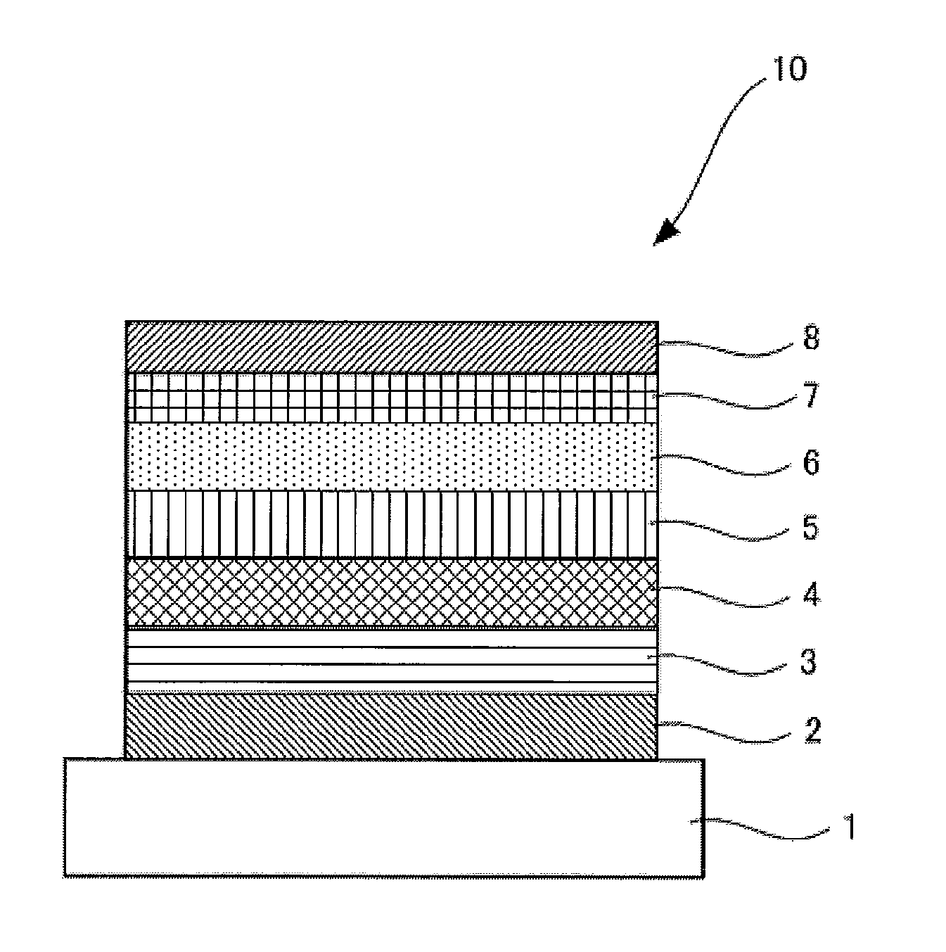
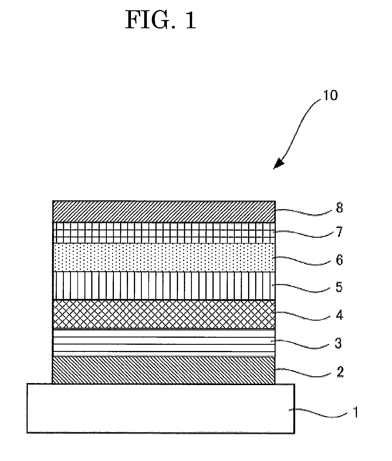
[0183]An organic electroluminescence element was produced in the same manner as in Comparative Example 1, except that D-1 represented by the above-described structural formula was used as a light emitting material, instead of Firpic.

example 2

Production of Organic Electroluminescence Element

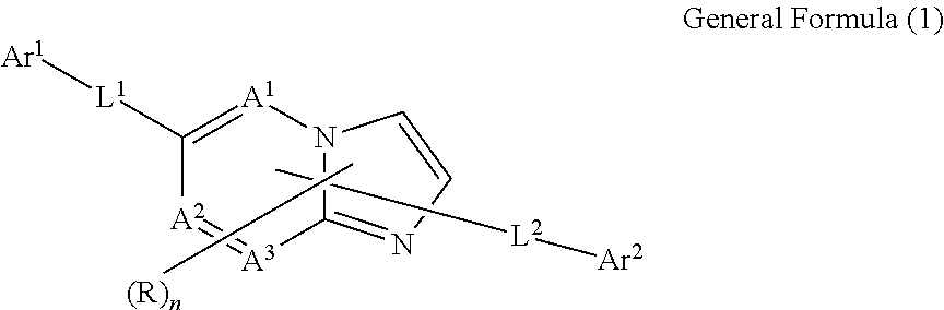
[0184]An organic electroluminescence element was produced in the same manner as in Example 1, except that Nitrogen-containing heterocyclic derivative 2 represented by the following structural formula was used as an electron transporting layer.

example 3

Production of Organic Electroluminescence Element

[0185]An organic electroluminescence element was produced in the same manner as in Example 1, except that Nitrogen-containing heterocyclic derivative 3 represented by the following structural formula was used as an electron transporting layer.


PUM


Abstract

An organic electroluminescence element including at least one organic layer including a light emitting layer, between an anode and a cathode, wherein at least one layer of the at least one organic layer contains at least one selected from specific nitrogen-containing heterocyclic derivatives, and at least one layer of the at least one organic layer contains a specific electron-transporting phosphorous light emitting material.

Description

BACKGROUND OF THE INVENTION[0001]1. Field of the Invention[0002]The present invention relates to an organic electroluminescence element (which may be, hereinafter, referred to as “organic electroluminescent element”, or “organic EL element)”.[0003]2. Background Art[0004]Organic electroluminescence elements have advantages of self-light emission and high-speed responsiveness and are expected to be used in flat panel display devices. Particularly, since a two-layered (multi-layered) organic EL element in which a hole-transporting organic thin film (hole transporting layer) and an electron transporting organic thin film (electron transporting layer) are laminated was reported, large-area light emitting element which emit light at a low voltage of 10 V or lower have attracted great interest. A multi-layered organic EL element basically includes a positive electrode, a hole transporting layer, a light emitting layer, an electron transporting layer and a negative electrode, among which th...

Claims


Application Information

Patent Timeline
Patent Type & Authority Applications(United States)
IPC IPC(8): H01L51/54
CPCC09K11/06C07F7/1848C09K2211/1011C09K2211/1029C09K2211/1044C09K2211/185H01L51/0072H01L51/0087H01L51/5016H01L51/5048H05B33/10C07F15/0033C07F15/006C07F15/0086C07F5/003C07F5/069C07F7/0812C09K2211/1007C07F7/1804H10K85/346H10K85/6572H10K50/14H10K50/11H10K2101/10
Inventor MASUI, KENSUKEHAYASHI, MASAYUKI
Owner UDC IRELAND
Why Eureka
Try Eureka