Side-viewing endoscope structure

Active Publication Date: 2011-09-22
MEDICAL INTUBATION TECH CORP
12 Cites 0 Cited by

AI-Extracted Technical Summary

Problems solved by technology

The endoscope would have largely limited applications if it could not have minimized dimensions.
(1) In manufacturing the currently available side-viewing endoscope using threaded connection for its front and rear capsules, spaces allowing for forming screw threads of predetermined pitch and depth must be reserved on the endoscope. By doing this, it would prevent the endoscope from being further miniaturized. Further, with the miniaturized size of the endoscope, it is difficult or even impossible to align the front and the rear capsule with each other for screwing them together. Thus, the threaded connection is not a suitable design for the miniaturized side-viewing endoscope.
(2) In the unit consisting of ...

Benefits of technology

[0008]When assembling the side-viewing endoscope structure of the present invention, the optical imaging unit can be disposed in the intermediate tubular section from the rear open end thereof, and the camera lens can be correspondingly immovably fitted in the inner diametrically reduced front open end of the intermediate tubular section. This design allows the intermediate tubular section of the side-viewing endoscope structure of the present invention to be sized in complete correspondence to that of the optical imaging unit to thereby save the space occupied by the intermediate tubular section, enabling the side-viewing endoscope structure to have a minimized volume. Further, in the present invention, the coupling portion of the front tubular section and the rear cap are firm...

Abstract

The present invention discloses a side-viewing endoscope structure including a front tubular section, an intermediate tubular section, a rear cap and an optical imaging unit. The front tubular section includes a tube, a reflector holder, and a reflector. The tube includes a main body and a coupling portion. The reflector holder is fitted in the main body of the tube and provided on one side of an outer wall surface thereof. The reflector is arranged on the reflector holder. A length of the intermediate tubular section has a reduced outer diameter to match the coupling portion. The rear cap has a rear wall provided with a cable hole. The optical imaging unit is located in the intermediate tubular section and the rear cap, and includes a flexible printed circuit board, a camera lens, a light source and a cable so as to transmit images.

Application Domain

Technology Topic

Image

  • Side-viewing endoscope structure
  • Side-viewing endoscope structure
  • Side-viewing endoscope structure

Examples

  • Experimental program(1)

Example

[0014]The present invention will now be described with a preferred embodiment thereof and with reference to the accompanying drawings. It is understood the accompanying drawings are illustrated only for assisting in describing the present invention and are not necessarily in compliance with the exact or precise size proportion and part arrangement of a real product manufactured through implementing the present invention. Therefore, the size proportion and part arrangement shown in the accompanying drawings are not intended to limit the present invention, which is intended to be limited only by the appended claims.
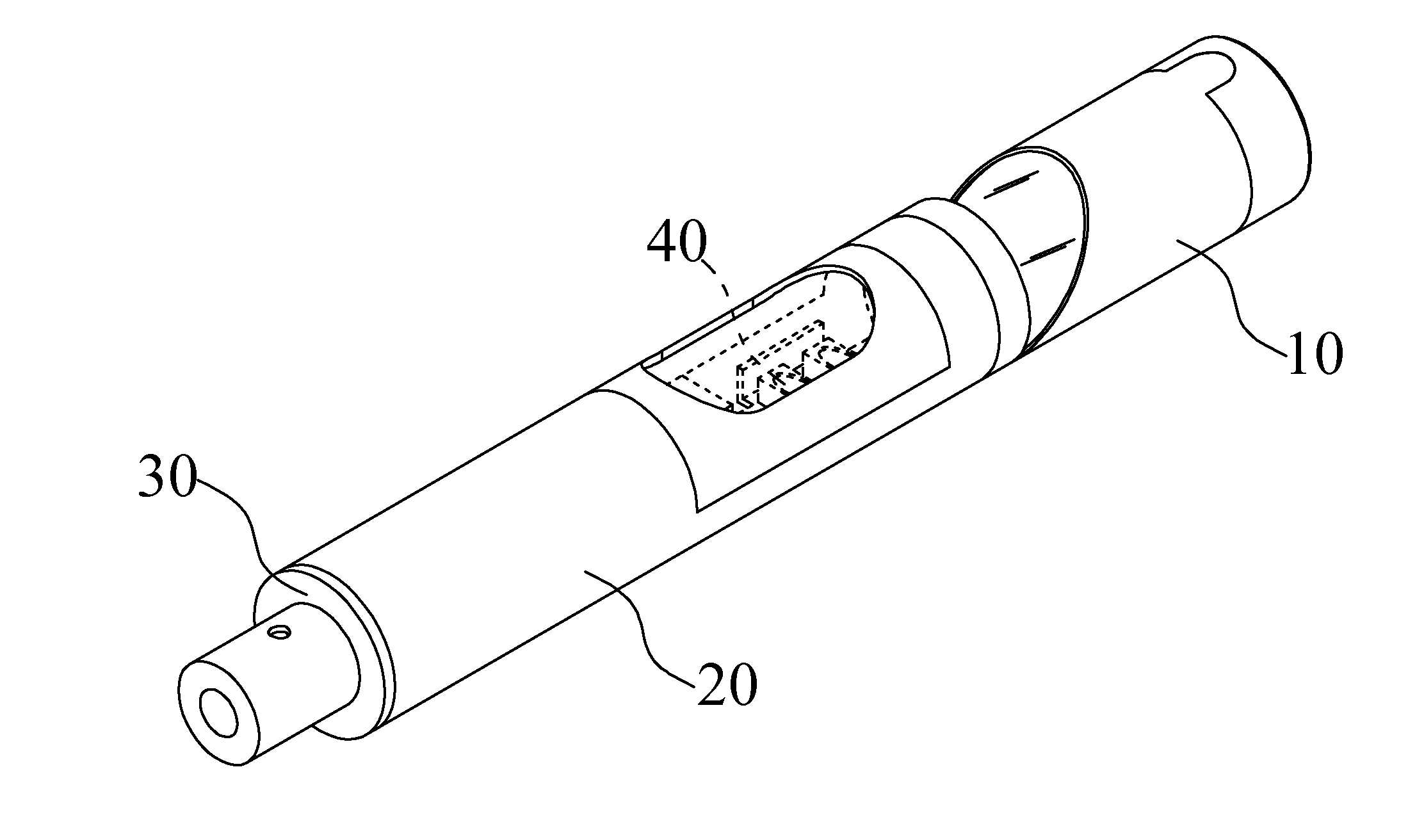
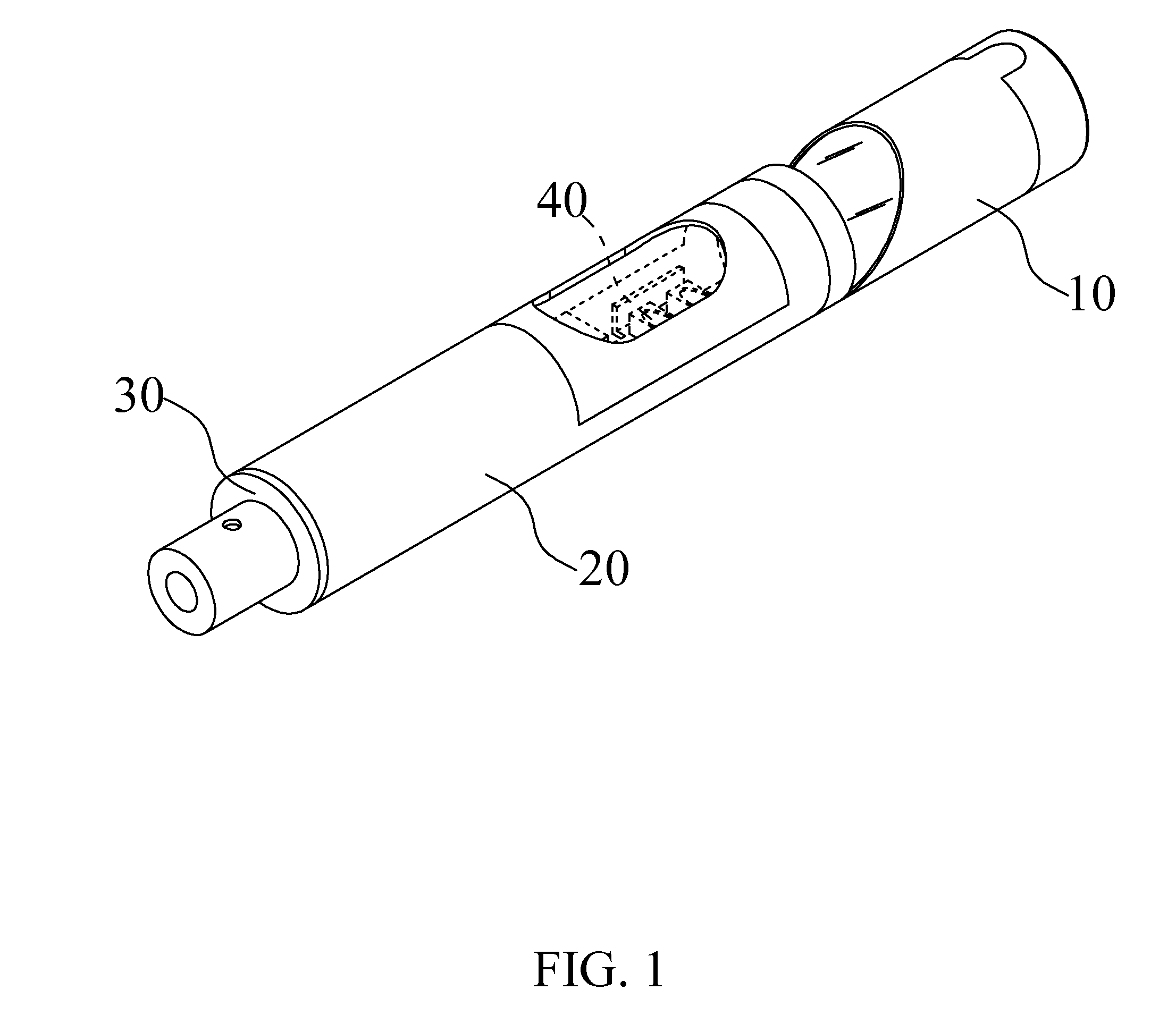
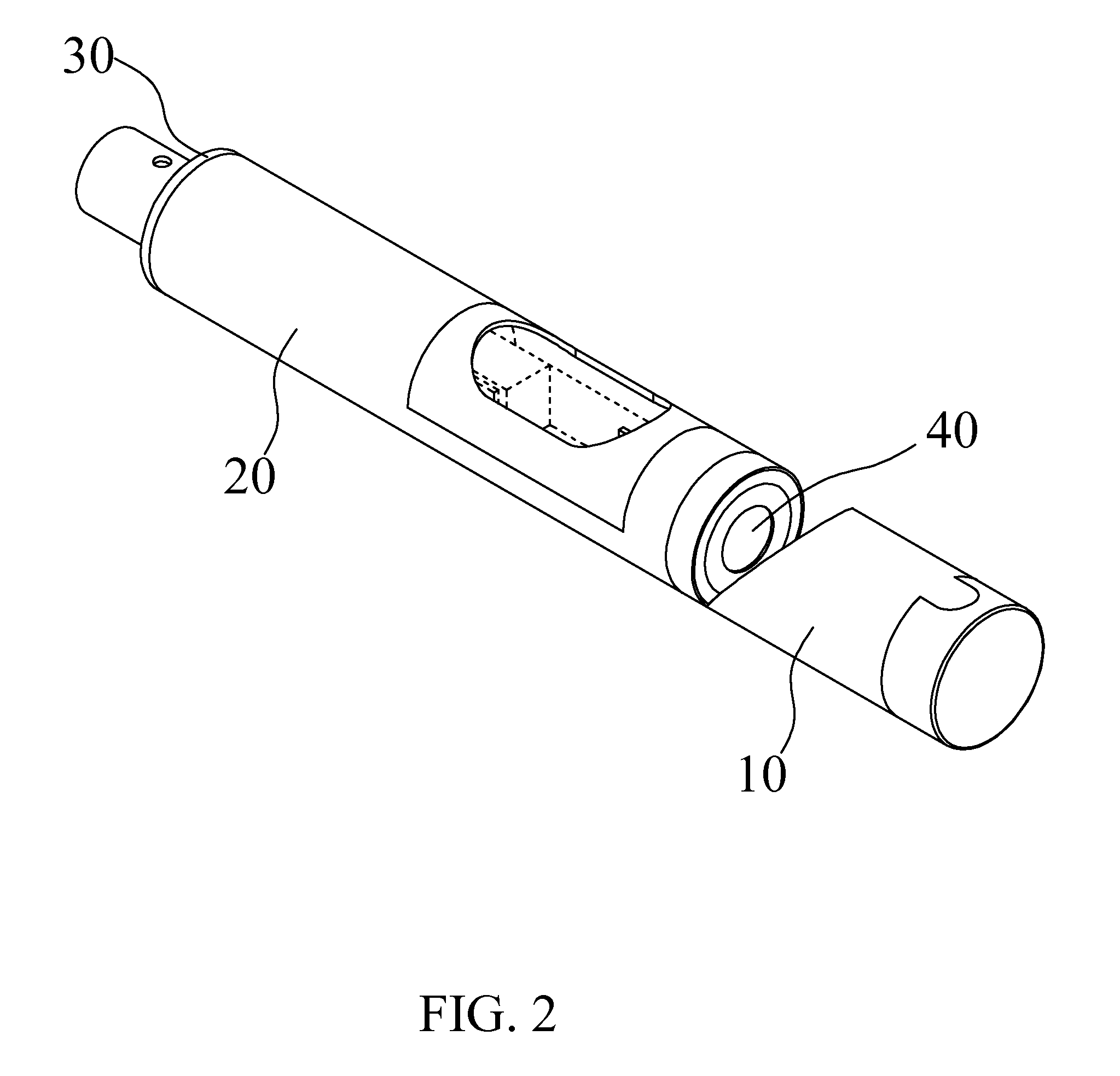
[0015]Please refer to FIGS. 1 to 4, in which a side-viewing endoscope structure according to an embodiment of the present invention is shown. As shown, the side-viewing endoscope structure of the present invention includes a front tubular section 10, an intermediate tubular section 20, a rear cap 30, and an optical imaging unit 40.
[0016]The front tubular section 10 includes a tube 11, a reflector holder 12, and a reflector 13.
[0017]The tube 11 includes a main body 111 and a coupling portion 112. The main body 111 is an elongated hollow cylindrical shell having a beveled rear open end. The beveled rear open end of the main body 111 may have an inclination angle ranged between 30 and 60 degrees. The main body 111 has a front open end, on an upper side of which a first aligning and engaging portion 1111 is formed. In the illustrated embodiment, the first aligning and engaging portion 1111 is in the form of a forward projection. The coupling portion 112 is in the form of a ring-shaped sleeve being correspondingly connected to a rear lower side of the beveled rear open end of the main body 111.
[0018]The reflector holder 12 is axially and immovably fitted in the main body 111 of the tube 11 with a beveled rear end wall 121 of the reflector holder 12 flushing with the beveled rear open end of the main body 111 of the tube 11. The reflector holder 12 is provided on one side of an outer wall surface thereof with a second aligning and engaging portion 122 corresponding to the first aligning and engaging portion 111 on the main body 111 of the tube 11. In the illustrated embodiment of the present invention, the second aligning and engaging portion 122 is in the form of a rear-opened recess. By aligning and engaging the projection 1111 with the recess 122, a user can quickly and correctly fitting the reflector holder 12 in the tube 11.
[0019]The reflector 13 is correspondingly arranged on the beveled rear end wall 121 of the reflector holder 12, so that light laterally projected onto the reflector 13 is refracted by the reflector 13 toward the coupling portion 112.
[0020]The intermediate tubular section 20 is a long tubular shell having a front and a rear open end. A length of the intermediate tubular section 21 at the front open end has a reduced outer diameter to match an inner diameter of the coupling portion 112, so as to fitly insert into the coupling portion 112 and become fixed thereto. A glue material or other equivalent sealing means may be applied on a contact surface between the intermediate tubular section 20 and the coupling portion 112 to secure the connection of them to each other. The intermediate tubular section 20 is provided on one side of a peripheral wall thereof with a through opening to serve as a light window 21. A transparent hood 22 is fixedly mounted on the light window 21 to cover the same.
[0021]The rear cap 30 is an enclosure having a front open end for correspondingly extending into the rear open end of the intermediate tubular section 20. Again, a glue material or other equivalent sealing means may be applied on a contact surface between the intermediate tubular section 20 and the rear cap 30 to secure the connection of them to each other. The rear cap 30 has a rear wall 31 that is provided with a cable hole 311 for a cable to extend therethrough. A portion of the rear wall 31 surrounding the cable hole 311 is rearward extended to provide a cable guide 32.
[0022]The optical imaging unit 40 is axially extended into and fixedly located in the intermediate tubular section 20 and the rear cap 30. The optical imaging unit 40 includes a flexible printed circuit board 41, a camera lens 42 located at a front end of the flexible printed circuit board 41 to correspondingly immovably fit in the front open end of the intermediate tubular section 20 with a front end of the camera lens 42 flushing with the front open end of the intermediate tubular section 20, a light source component 43 located on the flexible printed circuit board 41 behind the camera lens 42 to correspond to the light window 21 provided on the intermediate tubular section 20, and a cable 44 for transmitting images connected to a rear part of the flexible printed circuit board 41 and rearward extended through the cable hole 311 and the cable guide 32 on the rear cap 30 to connect to an image display instrument.
[0023]The present invention is characterized in that, when assembling the side-viewing endoscope structure, the optical imaging unit 40 can be disposed in the intermediate tubular section 20 from the rear open end thereof, and the camera lens 42 can be correspondingly immovably fitted in the inner diametrically reduced front open end of the intermediate tubular section 20. This design allows the intermediate tubular section 20 of the side-viewing endoscope structure of the present invention to be sized in complete correspondence to that of the optical imaging unit 40 without causing any waste of the space in the intermediate tubular section 20. Thus, the side-viewing endoscope structure of the present invention can have a minimized volume. Further, in the present invention, the coupling portion 112 of the front tubular section 10 and the rear cap 30 are firmly connected to two ends of the intermediate tubular section 20 without using any threaded connection. Therefore, unlike the prior art side-viewing endoscope including two mutually screwed capsules that cause difficulty in further reduction of the overall volume of the endoscope and could not be quickly aligned and assembled due to the small size thereof, the side-viewing endoscope structure of the present invention can have effectively reduced overall volume to largely relieve the patient's discomfort when the endoscope passes through the patient's throat for examining the inside of the patient's body. The side-viewing endoscope structure according to the present invention can also be advantageously applied in industrial and other purposes for detection in an extremely small space. Therefore, the present invention is highly practical for use to create good gains.
[0024]The present invention has been described with a preferred embodiment thereof and it is understood that many changes and modifications in the described embodiment can be carried out without departing from the scope and the spirit of the invention that is intended to be limited only by the appended claims.

PUM

no PUM

Description & Claims & Application Information

We can also present the details of the Description, Claims and Application information to help users get a comprehensive understanding of the technical details of the patent, such as background art, summary of invention, brief description of drawings, description of embodiments, and other original content. On the other hand, users can also determine the specific scope of protection of the technology through the list of claims; as well as understand the changes in the life cycle of the technology with the presentation of the patent timeline. Login to view more.

Similar technology patents

Multifunctional torque wrench

ActiveUS20200156223A1Minimize volumeFacilitates convenienceSpannersWrenchesPhysicsFastener
Owner:HU BOBBY

Needle storage magazine assembly

ActiveUS20190111216A1Minimize in sizeMinimize volumeAmpoule syringesTube connectorsBiomedical engineering
Owner:EMBECTA CORP

Personal mobility

PendingUS20210393455A1Minimize volumeFacilitate storageFoldable cyclesVehicular energy storageAutomotive engineeringHigh voltage battery
Owner:HYUNDAI MOTOR CO LTD +1

Classification and recommendation of technical efficacy words

  • Reduce volume
  • Minimize volume

Implant release mechanism

ActiveUS20080140178A1Reduce volumeReduce outer diameterStentsOcculdersDilatorStent
Owner:COOK MEDICAL TECH LLC

Flash storage chip and flash array storage system

ActiveUS20080052451A1Reduce volumeImprove data transmission rateMemory adressing/allocation/relocationData transmissionPCI Express
Owner:PHISON ELECTRONICS

Devices and methods for placement of partitions within a hollow body organ

InactiveUS20070167960A1Reduce volumeSuture equipmentsStapling toolsTissue acquisitionBody organs
Owner:ETHICON ENDO SURGERY INC

Rotary Pawl Glove Box Latch

ActiveUS20070216173A1Raise pivot pointMinimize volumeNoise-prevention/anti-rattling lockingAnti-theft cycle devicesLocking plate
Owner:SOUTHCO

Thin Optical Imaging module of a Biometric Apparatus

ActiveUS20160227081A1Minimize volumeIncrease processing speedTelevision system detailsPrismsFingerprintImage sensor
Owner:TRUE LIGHT

Wire tensioner

Owner:SAMWOO GEOTECH
Why Eureka
Try Eureka