
Remote-controlled actuator

a remote control and actuator technology, applied in the field of remote control actuators, can solve the problems of difficult widening the working, small gap between the living bone and the artificial joint, and difficulty in processing the artificial joint insertion hole, etc., to achieve favorable lubrication of the bearing, reduce and increase the pressure of liquid lubricant

Inactive Publication Date: 2011-09-22
NTN CORP
View PDF12 Cites 11 Cited by
  • Summary
  • Abstract
  • Description
  • Claims
  • Application Information

AI Technical Summary

Benefits of technology

[0017]An object of the present invention is to provide a remote control actuator of a type, in which the attitude of the tool coupled to the distal end of the elongated pipe section can be changed by remote control and which is capable of performing a processing under an optimum condition at all times and, also, a remote controlled actuator capable of halting the rotation of the tool or inhibiting the tool from being rotated in the event of occurrence of an abnormality.

Problems solved by technology

Whatever the pipe take any shape, the working range of the tool is limited by the shape of the pipe and, therefore, it is difficult to widen the working range of the tool to process the artificial joint insertion hole so that the living bone and the artificial joint may can have smooth contact surfaces and, yet, the gap between the living bone and the artificial joint may be small while skin incision and muscular scission are minimized at the same time.
Accordingly, the processing of the artificial joint insertion hole is more difficult to achieve than generally considered.
It has, however, been found that since the tool is connected to the distal end of the elongated pipe, disposition of a mechanism for changing the attitude of the tool is considerably limited and, therefore, artifices are required to overcome those limitations.

Method used


Image

  • Remote-controlled actuator
  • Remote-controlled actuator
  • Remote-controlled actuator

Examples


first embodiment

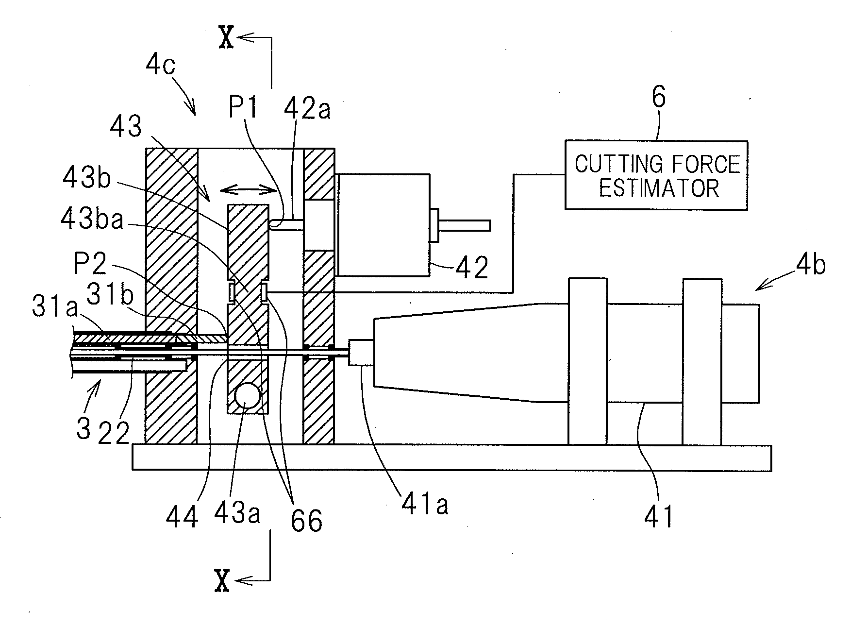
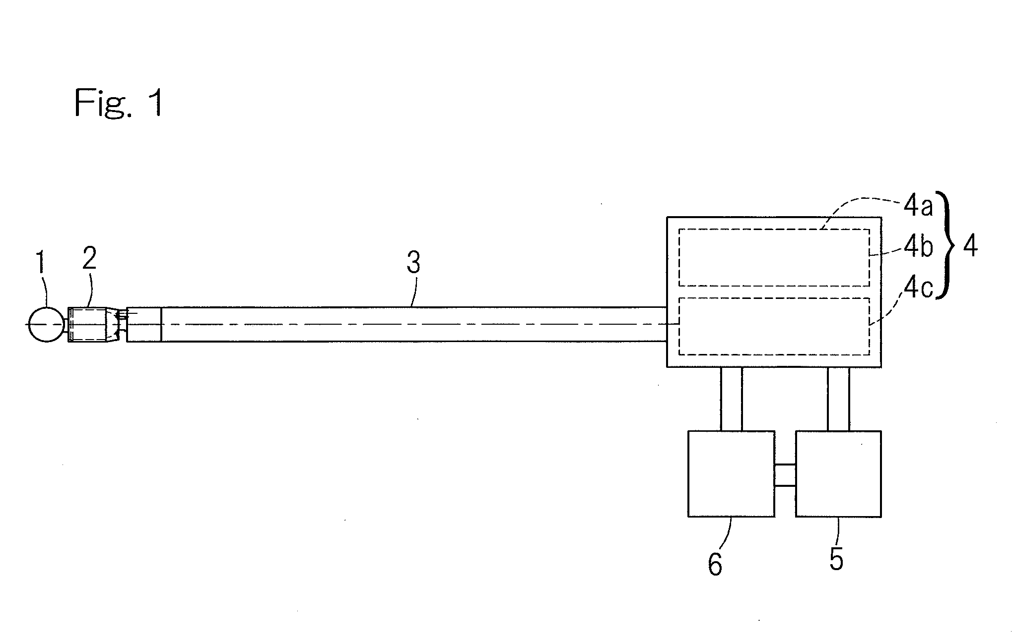
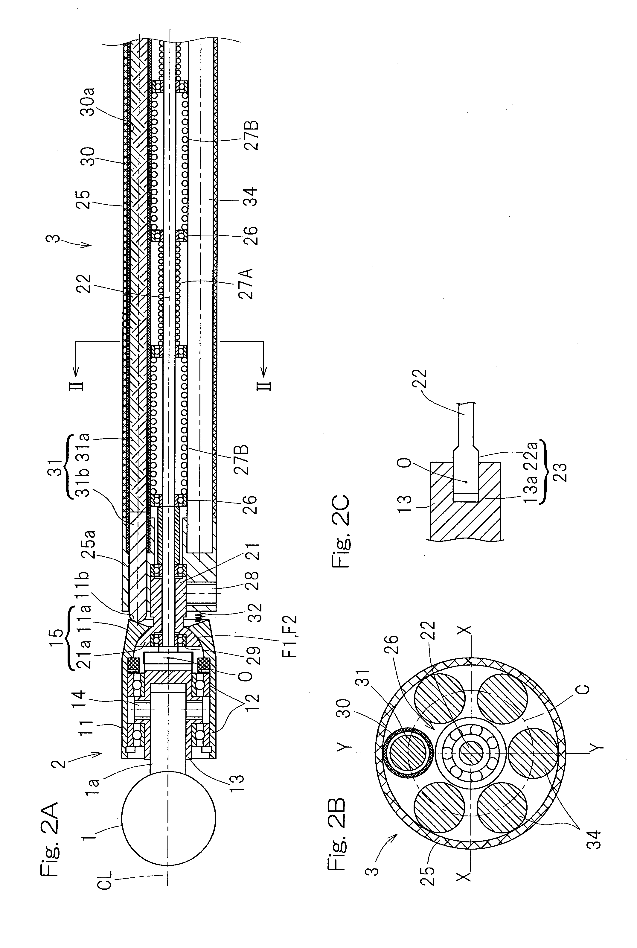
[0089]A first preferred embodiment of the present invention will now be described with particular reference to FIG. 1 to FIGS. 3A and 3B. Referring to FIG. 1, a remote controlled actuator according to the present invention includes a distal end member 2 for holding a rotary tool 1, an elongated spindle guide section 3 having a distal end to which the distal end member 2 is coupled for displacement in attitude, a drive unit housing 4a to which a proximal end of the spindle guide section 3 is coupled, a controller 5 for controlling a tool rotating drive mechanism 4b and an attitude altering drive mechanism 4c, both accommodated within the drive unit housing 4a, and a cutting force estimator 6 for estimating a cutting force during the processing. The drive unit housing 4a cooperates with the built-in tool rotating drive mechanism 4b and attitude altering drive mechanism 4c to form a drive unit 4.

[0090]As best shown in FIGS. 2A to 2C, the distal end member 2 includes a generally or subs...

second embodiment

[0128]FIGS. 11A and 11B illustrate a second preferred embodiment of the present invention. The remote controlled actuator according to this second embodiment is of a design, in which the two guide pipes 30 are provided at the peripheral positions spaced 180° in phase from each other within the outer shell pipe 25 and the attitude altering member 31 is reciprocally movably inserted within guide holes 30a, which are inner diametric holes of the guide pipes 30. Between those two guide pipes 30, a plurality of reinforcement shafts 34 are arranged on the same pitch circle as that of the guide pipes 30. No restoring elastic member 32 is provided. The guide faces F1 and F2 are spherical surfaces each having the center of curvature lying at the point O or cylindrical surfaces each having a lateral X-axis as a longitudinal axis passing through the point O.

[0129]The drive unit 4 (not shown in FIG. 11A or 11B) is provided with two attitude altering drive sources 42 (not shown in FIG. 11A or 11...

third embodiment

[0132]FIGS. 12A and 12B illustrate a third preferred embodiment of the present invention. The remote controlled actuator according to this third embodiment makes use of three guide pipes 30 disposed within the outer shell pipe 25 and positioned at respective circumferential position spaced 120° in phase from each other within the outer shell pipe 25 and, correspondingly, three attitude altering members 31 accommodated within respective guide holes 30a, which are inner diametric holes of those guide pipes 30, for reciprocal movement relative to the associated guide pipes 30. Between the three guide pipes 30, a plurality of reinforcement shafts 34 are arranged on the same pitch circle as that of the guide pipes 30. No restoring elastic member 32 is provided. The guide surfaces F1 and F2 represents spherical surface having respective centers of curvature lying at the point O and the distal end member 2 can be tilted in any desired direction.

[0133]The drive unit 4 is provided with three...


PUM

PropertyMeasurementUnit
Temperatureaaaaaaaaaa
Pressureaaaaaaaaaa
Strain pointaaaaaaaaaa

Abstract

A remote-controlled actuator includes a spindle guide section of an elongated shape, a distal end member fitted to a distal end of the spindle guide section for alteration in attitude and rotatably supporting a tool, and a drive unit housing having a base end of the spindle guide section connected therewith. A rotary shaft for transmitting rotation of a tool rotation drive source within the drive unit housing to the tool and an attitude altering member for altering the attitude of the distal end member by the drive of an attitude altering drive source within the drive unit housing are accommodated within the spindle guide section. A cutting force estimator is provided for estimating the magnitude of at least one component force of a principle force, a radial force and a feed force in a cutting force which the tool applies to a work to be processed.

Description

CROSS REFERENCE TO THE RELATED APPLICATION[0001]This application is a continuation application, under 35 U.S.C. §111(a) of international application No. PCT / JP2009 / 006286, filed Nov. 20, 2009, which claims priority to Japanese patent applications No. 2008-302091, filed Nov. 27, 2008, and No. 2009-013002, filed Jan. 23, 2009, the entire disclosure of both of which is herein incorporated by reference as a part of this application.BACKGROUND OF THE INVENTION[0002]1. Field of the Invention[0003]The present invention relates to a remote controlled actuator for use in medical and machine processing fields and capable of changing the attitude of a machine tool.[0004]2. Description of Related Art[0005]Remote controlled actuators are currently available; some are used in the medical field for osteal treatment and some are used in the mechanical processing field for drilling and cutting a bone. Any of those remote controlled actuators controls by remote control a machine tool fitted to a dist...

Claims


Application Information

Patent Timeline
IPC IPC(8): A61B17/00
CPCA61B17/1626A61B17/1631B23B45/005A61B17/1668B23B39/14A61B17/1642
Inventor ISOBE, HIROSHINISHIO, YUKIHIRONAGANO, YOSHITAKAOZAKI, TAKAYOSHI
Owner NTN CORP
Learn More