Ignition plug cooling device of vehicle-use engine

a technology of cooling device and ignition plug, which is applied in the direction of electric ignition installation, machines/engines, mechanical equipment, etc., can solve the problems of insufficient space in the cylinder head, inability to cool the second ignition plug on the outlet side of the air flow passage, and inability to achieve the cooling effect of the first, so as to increase the degree of freedom in the arrangement of the first effect of efficient cooling

Active Publication Date: 2011-09-29
HONDA MOTOR CO LTD
View PDF10 Cites 12 Cited by
  • Summary
  • Abstract
  • Description
  • Claims
  • Application Information

AI Technical Summary

Benefits of technology

[0007]The present invention has been made under such circumstances, and it is an object of the present invention to provide an ignition plug cooling device of a vehicle engine which can efficiently cool both the first and second ignition plugs while increasing the degree of freedom in the arrangement of the first and second ignition plugs.

Problems solved by technology

In the above-mentioned conventional ignition plug cooling device of the vehicle engine, since the pair of ignition plugs is arranged in one air flow passage, the cooling property of the second ignition plug arranged on an outlet side of the air flow passage is inevitably inferior to the cooling property of the first ignition plug arranged on an inlet side of the air flow passage.
However, the actual circumstance is that there is not a sufficient space in the cylinder head which allows the formation of two independent air flow passages which individually cool the first and second ignition plugs.

Method used


Image

  • Ignition plug cooling device of vehicle-use engine
  • Ignition plug cooling device of vehicle-use engine
  • Ignition plug cooling device of vehicle-use engine

Examples


Embodiment Construction

[0030]Hereinafter, an embodiment of the present invention is explained in conjunction with attached drawings.

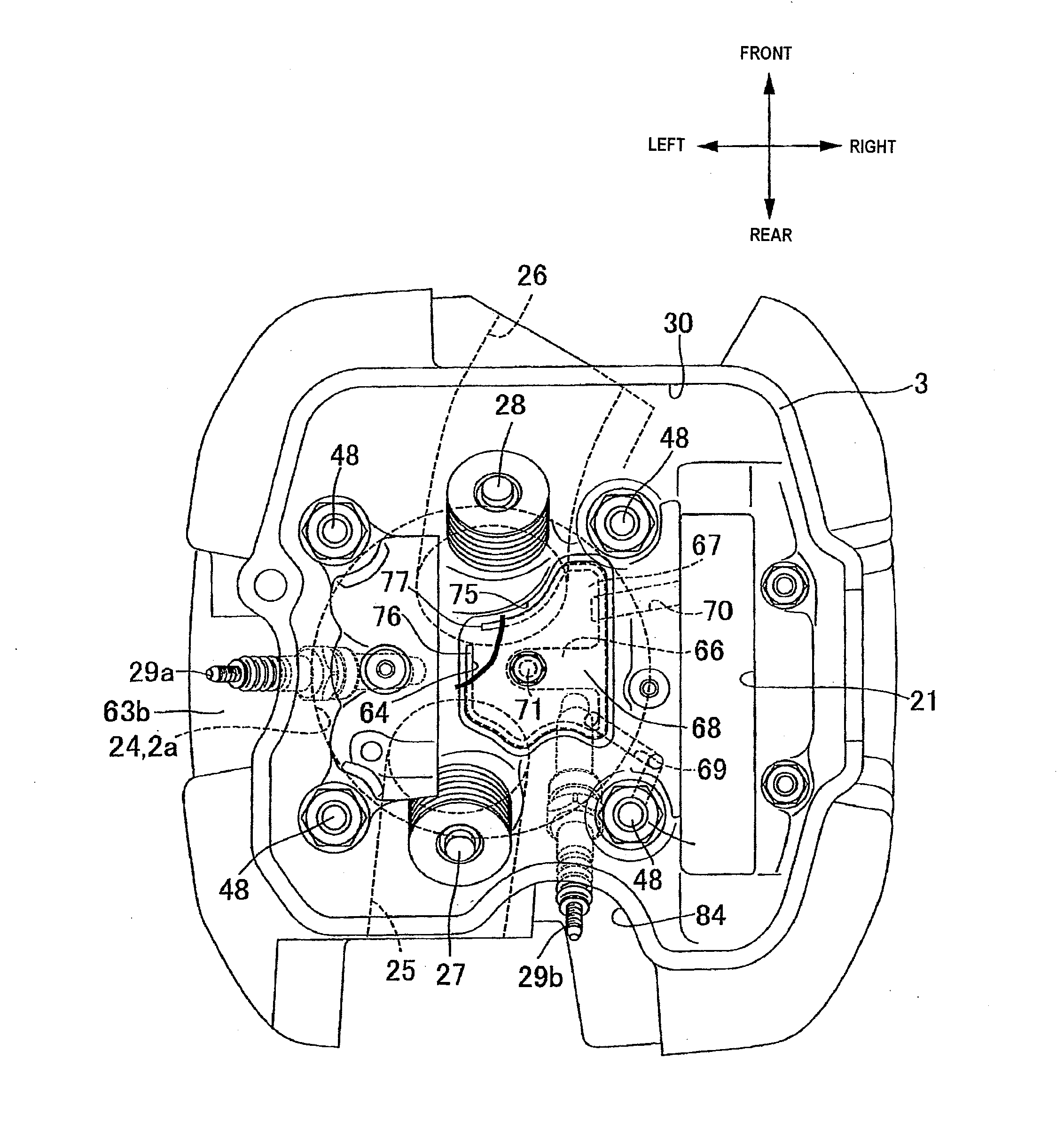
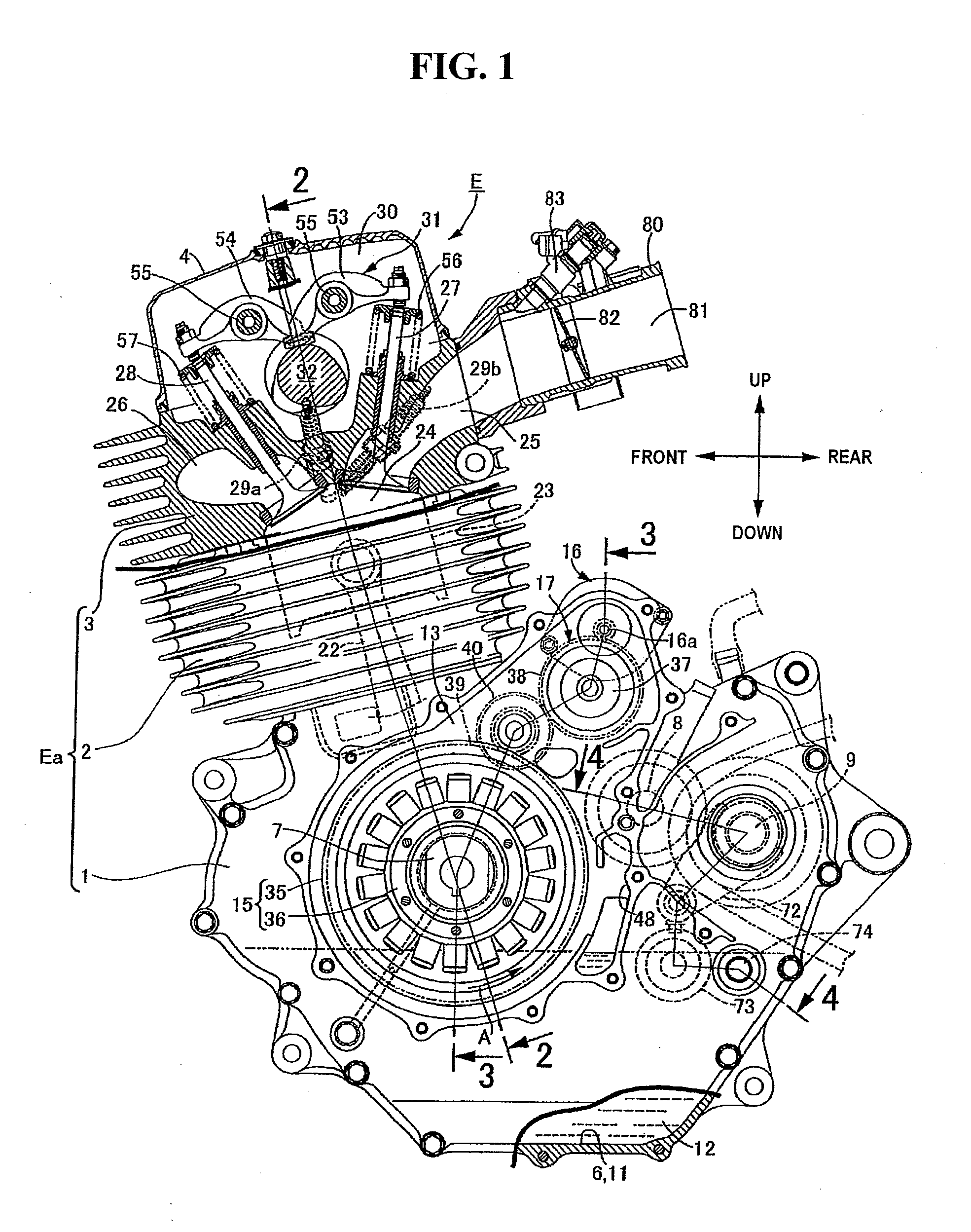
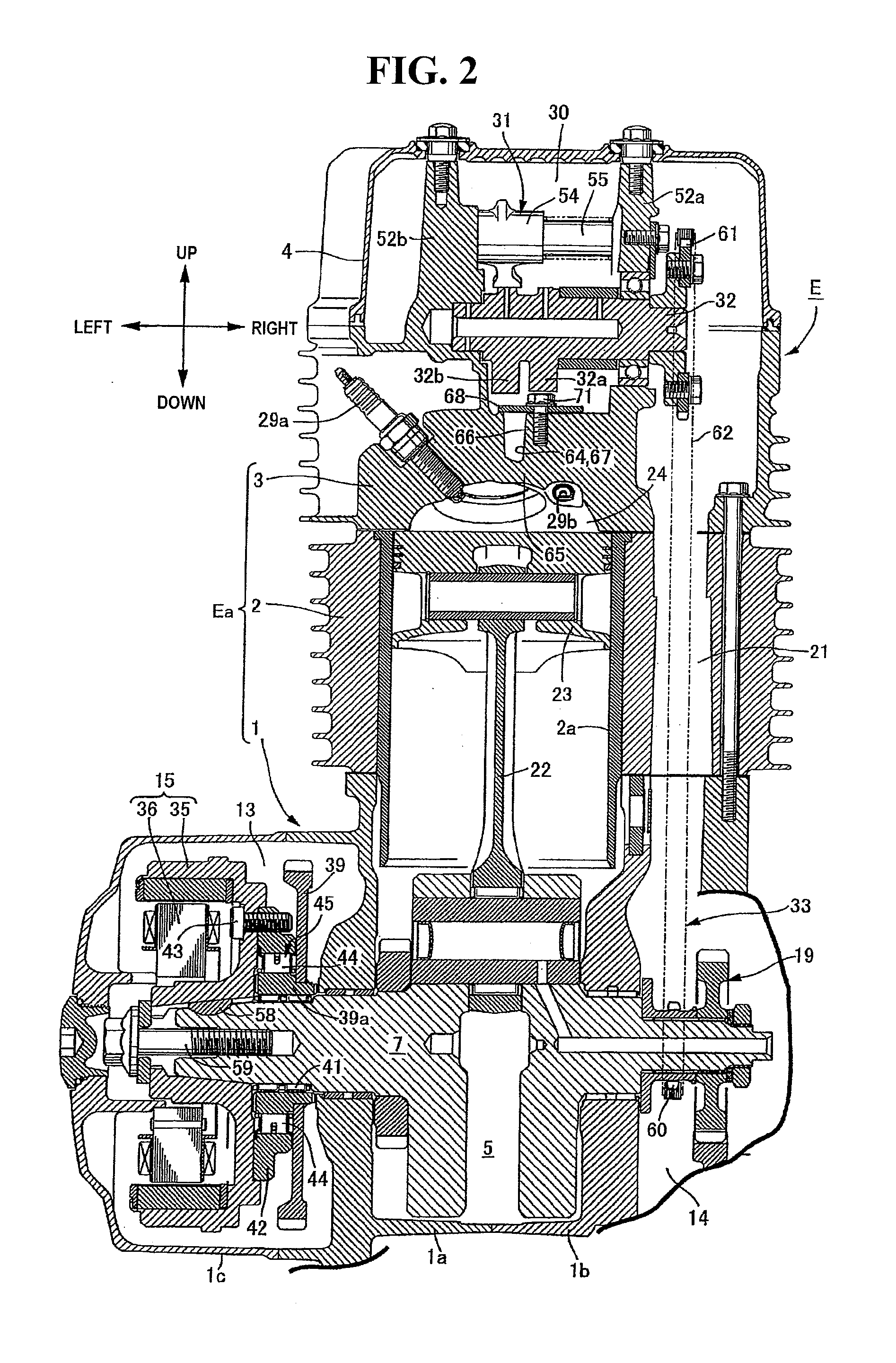
[0031]In FIG. 1 to FIG. 4, an engine body Ea of an engine E which is mounted on a motorcycle is constituted of a crankcase 1, a cylinder block 2 which is joined to an upper surface of the crankcase 1 in an erected manner using bolts, and a cylinder head 3 which is joined to an upper end surface of the cylinder block 2 using bolts. A head cover 4 is joined to an upper end surface of the cylinder head 3 using bolts.

[0032]In the following explanation, the directions of “front and rear” and “left and right” correspond to the directions of “front and rear” and “left and right” of the motorcycle with the engine E mounted thereon.

[0033]Further, the above-mentioned crankcase 1 includes a left case body 1a and a right case body 1b which are joined to each other using bolts, a left case cover 1c which is joined to an outer end surface of the left case body 1a using bolts, and a right c...


PUM


Abstract

An ignition plug cooling device of a vehicle engine for efficiently cooling the ignition plugs while increasing the freedom in the arrangement of the ignition plugs. A vehicle engine includes a first ignition plug and a second ignition plug for making respective electrodes thereof face a combustion chamber and are mounted on a cylinder head. An air flow passage through which a flow of air passes and a cooling oil chamber through which lubrication oil for the engine passes are formed in the cylinder head. The first ignition plug is arranged in the air flow passage to enable a cooling of the first ignition plug by the flow of air which passes through the air flow passage. The second ignition plug is arranged adjacent to the cooling oil chamber to enable a cooling of an area around the second ignition plug by oil which passes through the cooling oil chamber.

Description

CROSS-REFERENCE TO RELATED APPLICATIONS[0001]The present application claims priority under 35 USC 119 to Japanese Patent Application No. 2010-066426 filed on Mar. 23, 2010 the entire contents of which are hereby incorporated by reference.BACKGROUND OF THE INVENTION[0002]1. Field of the Invention[0003]The present invention relates to an improvement of an ignition plug cooling device of a vehicle engine in which a first ignition plug and a second ignition plug which make respective electrodes thereof face a combustion chamber are mounted on a cylinder head having the combustion chamber and an intake port and an exhaust port which open in the combustion chamber.[0004]2. Description of Background Art[0005]An engine for a vehicle such as a motorcycle is known for enhancing output performance and low fuel consumption by increasing combustion efficiency. See, for example, Japanese Patent No. 4209440. A vehicle engine is known wherein a pair of first and second ignition plugs which makes re...

Claims


Application Information

Patent Timeline
Patent Type & Authority Applications(United States)
IPC IPC(8): F01P3/16
CPCF02F1/242F02F1/28F02F1/32F02P15/08F02F1/38F02F7/0004F02P15/02F02F1/36
Inventor TAKI, MASAFUMIKITADA, YOSHIHIRONISHI, TORU
Owner HONDA MOTOR CO LTD
Why Eureka
Try Eureka