Combi-valve for a blower driven ventilator

a technology of vacuum valves and ventilators, which is applied in the direction of valve details, valve arrangements, life-saving devices, etc., can solve the problems of reducing the resistance of the membrane, reducing the flow generated by the radial blower, and difficulty in controlling the flow for low flow settings. , to achieve the effect of reducing reducing or increasing the resistance caused by the membrane, and allowing flow control. more accurate and accura

a technology of vacuum valves and ventilators, which is applied in the direction of valve details, valve arrangements, life-saving devices, etc., can solve the problems of reducing the resistance of the membrane, reducing the flow generated by the radial blower, and difficulty in controlling the flow for low flow settings. , to achieve the effect of reducing reducing or increasing the resistance caused by the membrane, and allowing flow control. more accurate and accura

US20110232640A1Inactive Publication Date: 2011-09-29DRAGERWERK AG

Image

  • Combi-valve for a blower driven ventilator
  • Combi-valve for a blower driven ventilator
  • Combi-valve for a blower driven ventilator

Examples


Embodiment Construction

[0030]Referring to the drawings in particular, it is noted that the embodiments described in the following are merely examples. Modifications of these examples may be made by the person skilled in the art.

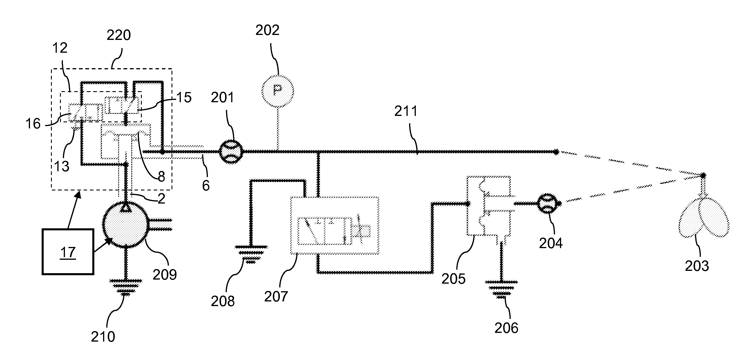
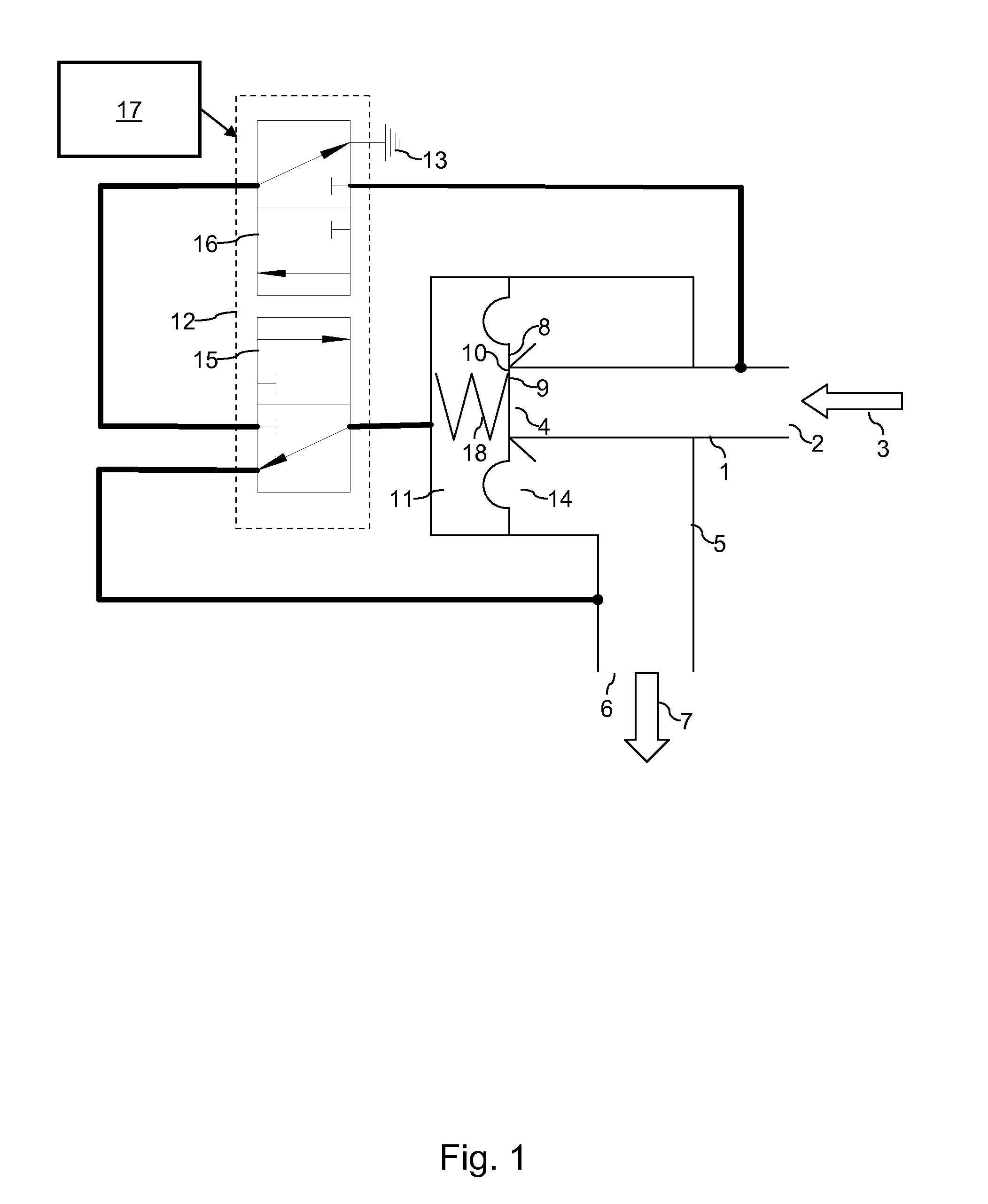
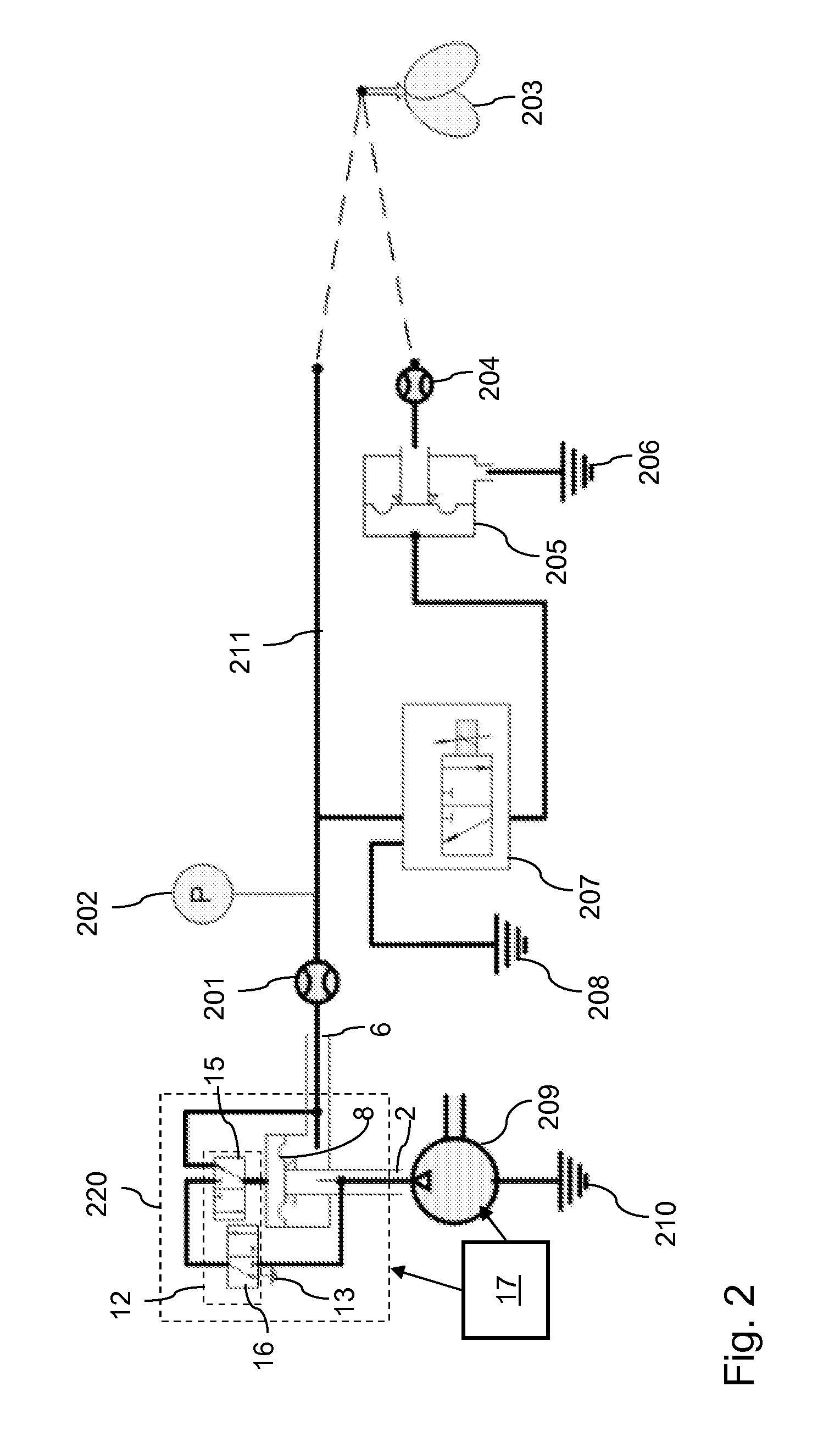
[0031]FIG. 1 shows a diagram of a valve assembly. The valve assembly may be incorporated in a mechanical ventilator, for example a blower driven ventilator. The blower may, for example, comprise a radial blower, as is known in the art per se. Alternatively, the valve assembly may be arranged for being connected with a blower-driven mechanical ventilator. FIG. 2 shows a diagram of a patient circuit comprising the valve assembly 220 of FIG. 1. In the figures, similar items have been given the same reference numerals.

[0032]The valve assembly 220, as illustrated in FIGS. 1 and 2, comprises a first conduit 1 for transporting fluid from a blower 209 to an orifice 4. This orifice 4 is referred to hereinafter as the first orifice 4. The fluid from the blower 209 arrives at an inlet 2 of th...


PUM


Abstract

A valve assembly for a blower driven ventilator has a first conduit (1), an inlet (2) for receiving fluid from the blower (209) and a first orifice (4). A second conduit (5) is provided with an outlet (6) for forwarding fluid to a patient (203). A membrane (8) includes a front side (9) and a back side (10), wherein at least part of the membrane (8) is movable between a closed position and an open position. A switching circuit (12) enables the selective opening and closing of a fluid connection between the cavity (11) and the blower (209) via the fluid inlet (2), a fluid connection between the cavity (11) and the patient (203) via the fluid outlet (6), and a fluid connection between the cavity (11) and ambient air (13). A control system (17) controls the switching circuit (12) during a ventilation operation of the blower (209).

Description

CROSS REFERENCE TO RELATED APPLICATIONS[0001]This application claims the benefit of priority under 35 U.S.C. ยง119 of European Patent Application EP 10 158 003.3 filed Mar. 26, 2010, the entire contents of which are incorporated herein by reference.FIELD OF THE INVENTION[0002]The invention relates to a valve assembly for a blower driven ventilator (also known as respirator). The invention further relates to a control system and method for controlling a valve assembly during a ventilation (respiration) operation of a blower.BACKGROUND OF THE INVENTION[0003]In a mechanical ventilator for providing ventilatory (respiratory) assistance to a patient, different kinds of sources may be used for providing an inspiratory gas mixture to the patient. For example, pressurized air and / or oxygen can be used. Alternatively, a blower can be used. Unlike a pressurized air or oxygen source, the blower has a low pneumatic impedance or resistance when the flow delivery is interrupted. This may typically...

Claims


Application Information

Patent Timeline
29 Sep 2011
Publication
US20110232640A1
IPC
A61M16/20
CPC
A61M16/20; A61M16/206; A61M16/204; A61M16/0069; A61M16/208
Inventors
VAN DIJK, GEERT; HERBEN, EUGENE