Accessory mounting device for saddle riding type vehicle

a technology for accessorizing devices and saddle riding, which is applied to vehicle components, cycle equipments, supplementary fittings, etc., can solve the problems of durability, easy restrictions on the mounting location and the mounting structure of the tank bag, etc., and achieve the effect of improving the versatility of the mounting device and simple structur

Active Publication Date: 2011-09-29
HONDA MOTOR CO LTD
View PDF5 Cites 7 Cited by
  • Summary
  • Abstract
  • Description
  • Claims
  • Application Information

AI Technical Summary

Benefits of technology

[0020]Furthermore, according to the accessory mounting device for a saddle riding type vehicle of the fourth aspect of the present invention, the angle between the front leg portion and the rear leg portion can be adjusted. In this sense, a versatility of the mounting device is improved, and the mounting device can be mounted on vehicle bodies of various shapes. In addition, a direction of the accessory can be adjusted by adjusting the angle of the holder. Since the common axes are employed, the mounting device has a simple structure.
[0021]Furthermore, according to the accessory mounting device for a saddle riding type vehicle of the fifth aspect of the present invention, the axes are allowed to move along the long holes, thus making it possible to adjust the angles of the front leg portion, the rear leg portion and the holder.

Problems solved by technology

However, when a filler cap is provided in the center of the fuel tank, a mounting location and a mounting structure of the tank bag are easily subjected to restrictions.
However, since a thick fabric, a resin or the like is particularly employed as the holder, the tank bag is inferior in U.V. toughness and oil resistance, thus giving rise to a problem of durability.
Particularly, an accessory will move around due to a vibration of a vehicle body or the like, when mounted on the tank by means of the flexible holders and thus not firmly fixed.

Method used


Image

  • Accessory mounting device for saddle riding type vehicle
  • Accessory mounting device for saddle riding type vehicle
  • Accessory mounting device for saddle riding type vehicle

Examples


first embodiment

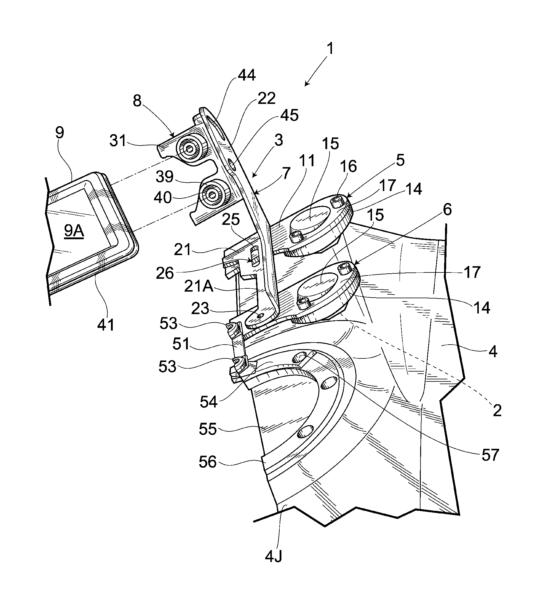
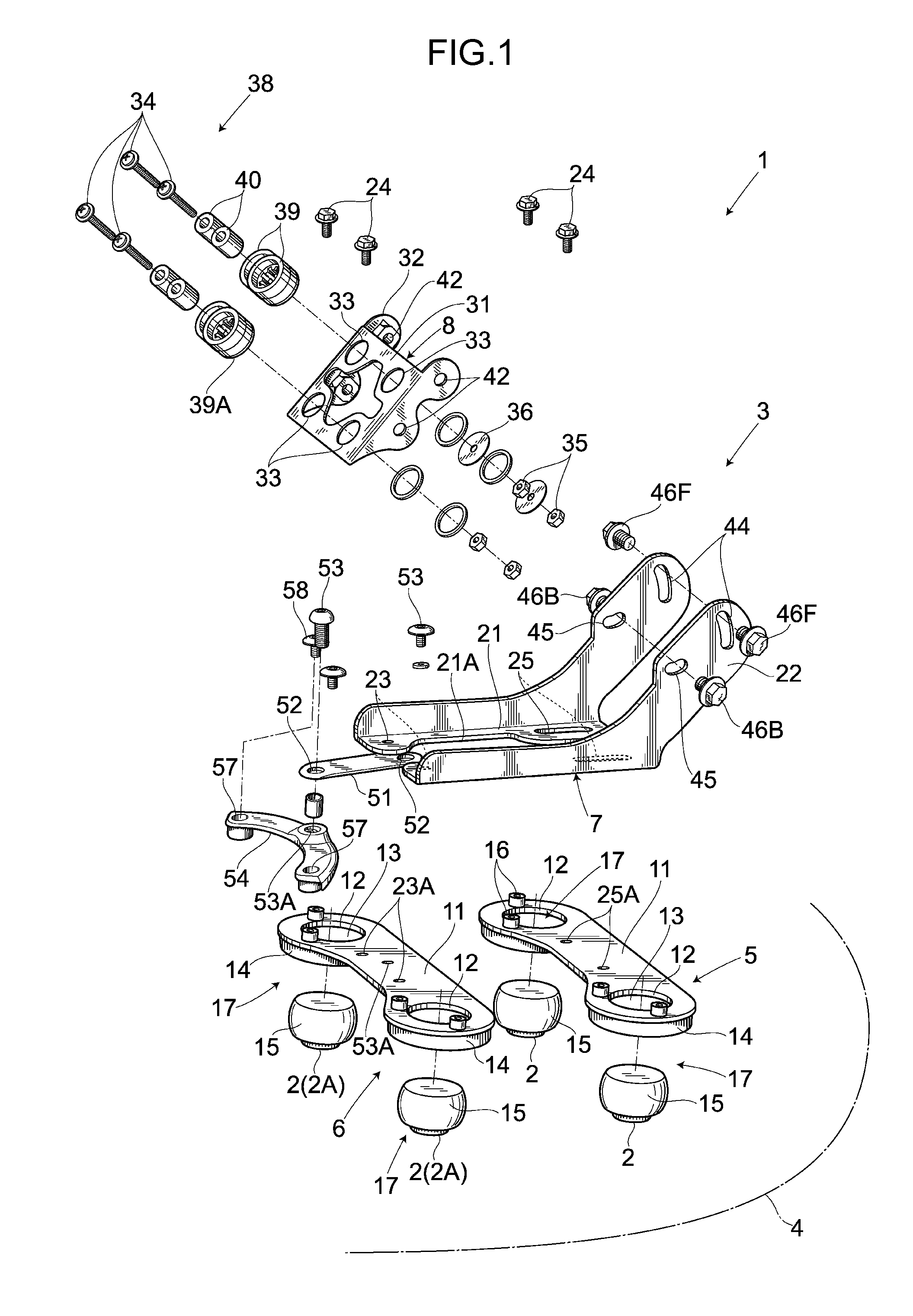
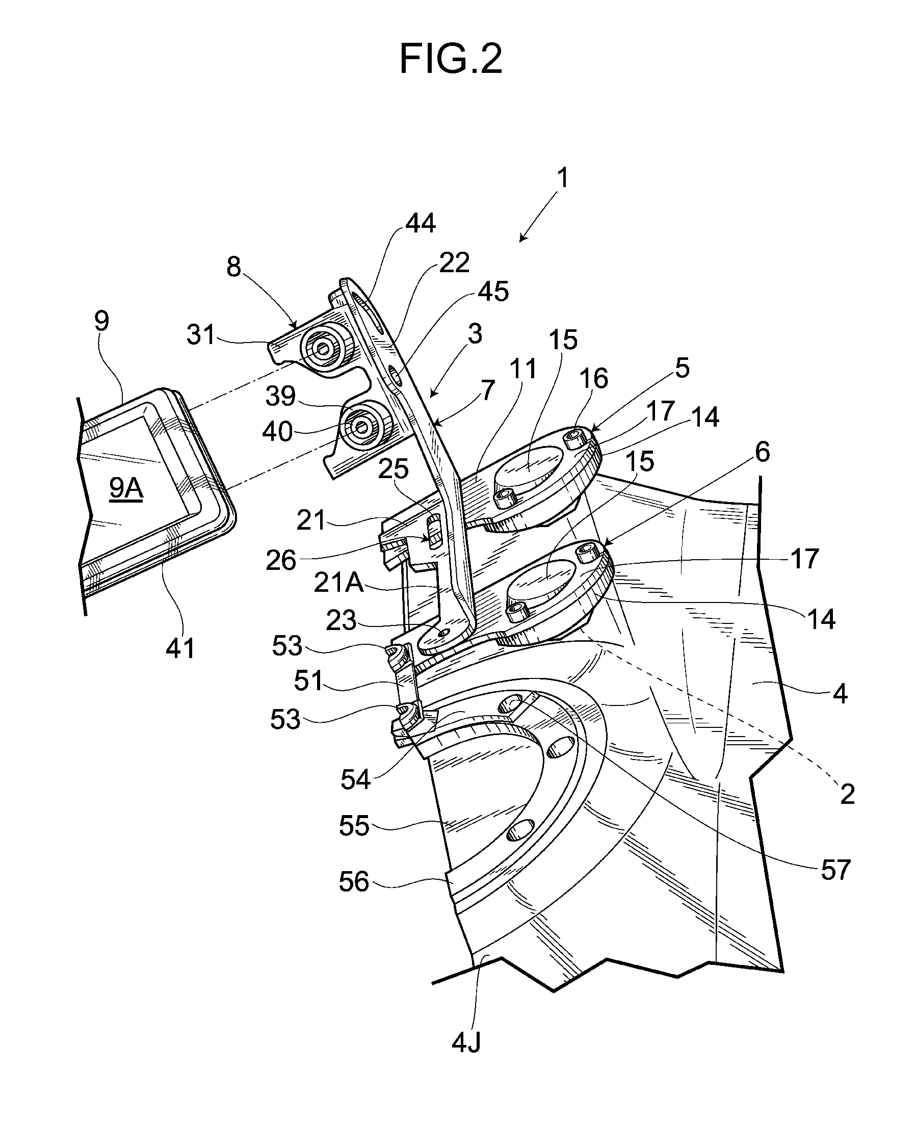
[0034]As shown in FIG. 1 through FIG. 6, an accessory mounting device 1 comprises a base body 3 detachably mounted on a vehicle body via permanent magnets 2, such vehicle body being located between a seat and a handlebar of a saddle riding type vehicle that is a motorcycle. In FIG. 1 through FIG. 6, there is shown an example in which the base body 3 is mounted on a fuel tank 4 serving as a vehicle body. According to the present embodiment, there are used as mounting members the permanent magnets 2 exhibiting sticking effects due to magnetic forces thereof. However, there can also be used as mounting members electromagnets, suction disks, planar fasteners, bonding layers or the like.

[0035]The base body 3 comprises a front leg portion 5 and a rear leg portion 6 that are made of metal. The front leg portion 5 and the rear leg portion 6 are coupled together by means of a receiving member 7 made of metal. A metallic bracket 8 serving as a holder is mounted on such receiving member 7 in a...

second embodiment

[0060]A second embodiment of the present invention is shown in FIG. 7 through FIG. 9. Same reference numbers are used to describe the same parts as those in the first embodiment, thereby omitting the detailed descriptions of such parts when describing the second embodiment. With regard to a receiving member 7 of a base body 3 of the present embodiment, a bottom plate 21 is formed shorter in a front-rear direction as compared to that of the first embodiment, and slide plates 22 are formed lower as compared to those of the first embodiment. In this sense, the receiving member 7 is formed into a shape that can be easily rotated. Further, there is provided a rear leg portion 6 composed of a left and a right leg portion main bodies 61, 61, individually. Such leg portion main body 61 is formed into a substantial “L” shape and integrally comprises a bottom plate 62 to which a permanent magnet 2 is attached by means of a spherical joint 17 and a side plate 63 provided on an inner side of th...

third embodiment

[0071]A third embodiment of the present invention is shown in FIG. 10. Same reference numbers are used to describe the same parts as those in the aforementioned embodiments, thereby omitting the detailed descriptions of such parts when describing the third embodiment. According to the present embodiment, a front leg portion 5 and a rear leg portion 6 are integrally provided on the receiving member 7 of the first embodiment. Specifically, through holes 12 are formed on both a left side and a right side of both a front side and a rear side of a bottom plate 21 of the receiving member 7, and permanent magnets 2 are attached to such through holes 12 by means of spherical joints 17. Further, a rear side of an opening 21A of the bottom plate 21 is in an opened condition, and the bottom plate 21 is formed into a substantial “U” shape when viewed from the top. The bottom plate 21 is so mounted on the fuel tank 4 that the opening 21A is adjusted to a filler cap 55, and a left and a right por...


PUM


Abstract

There is provided an accessory mounting device for a saddle riding type vehicle. An accessory mounting device for mounting a navigation device on a fuel tank comprises a base body on which the navigation device is mounted, and permanent magnets caused to stick to the fuel tank and thus allowing the base body to be mounted thereon. The permanent magnets are provided on the base body via spherical joints. In this sense, the permanent magnets are caused to stick to the fuel tank in a manner such that directions thereof are changed depending on a shape of the fuel tank, thus obtaining a stable mounting structure. Further, since there is no need to provide flexible members around the permanent magnets, an excellent durability is achieved. Furthermore, the base body comprises a bracket for holding the car navigation device, and an angle of the bracket can be adjusted.

Description

BACKGROUND OF THE INVENTION[0001]1. Field of the Invention[0002]The present invention relates to an accessory mounting device for a saddle riding type vehicle.[0003]2. Description of Related Art[0004]Conventionally, as a mounting device of this type, there has been known an electric component mounting device for two-wheeled vehicle composed of a fixation portion mounted on a tank or a handlebar of a two-wheeled vehicle, and a holder for holding an electric component. The fixation portion is provided on a vehicle body center line extending in a front-rear direction of the two-wheeled vehicle. The holder is so attached to the fixation portion that it can rotate about an axis of a left-right direction. There are also provided an upper receiving hardware and a lower receiving hardware that are screwed together via bolts, and are thus allowed to hold the handlebar therebetween and be fixed thereto. The fixation portion is fixed by means of the aforementioned bolts (e.g., see Japanese Pat...

Claims


Application Information

Patent Timeline
Patent Type & Authority Applications(United States)
IPC IPC(8): B60R11/00
CPCB62J2099/0033B62J99/00B62J50/225
Inventor NAKAJIMA, SHOICHI
Owner HONDA MOTOR CO LTD
Why Eureka
Try Eureka