Active target with height diversity

a radar target and height diversity technology, applied in the direction of measurement devices, radio wave direction/deviation determination systems, instruments, etc., can solve the problems of two signal paths that can interfere, either constructively or destructively, and the radar signal is not useful, so as to achieve low signal return strength, easy detection, and low signal power

a radar target and height diversity technology, applied in the direction of measurement devices, radio wave direction/deviation determination systems, instruments, etc., can solve the problems of two signal paths that can interfere, either constructively or destructively, and the radar signal is not useful, so as to achieve low signal return strength, easy detection, and low signal power

US20110234445A1Active Publication Date: 2011-09-29GUIDANCE NAVIGATION HLDG LTD

Image

  • Active target with height diversity
  • Active target with height diversity
  • Active target with height diversity

Examples


Embodiment Construction

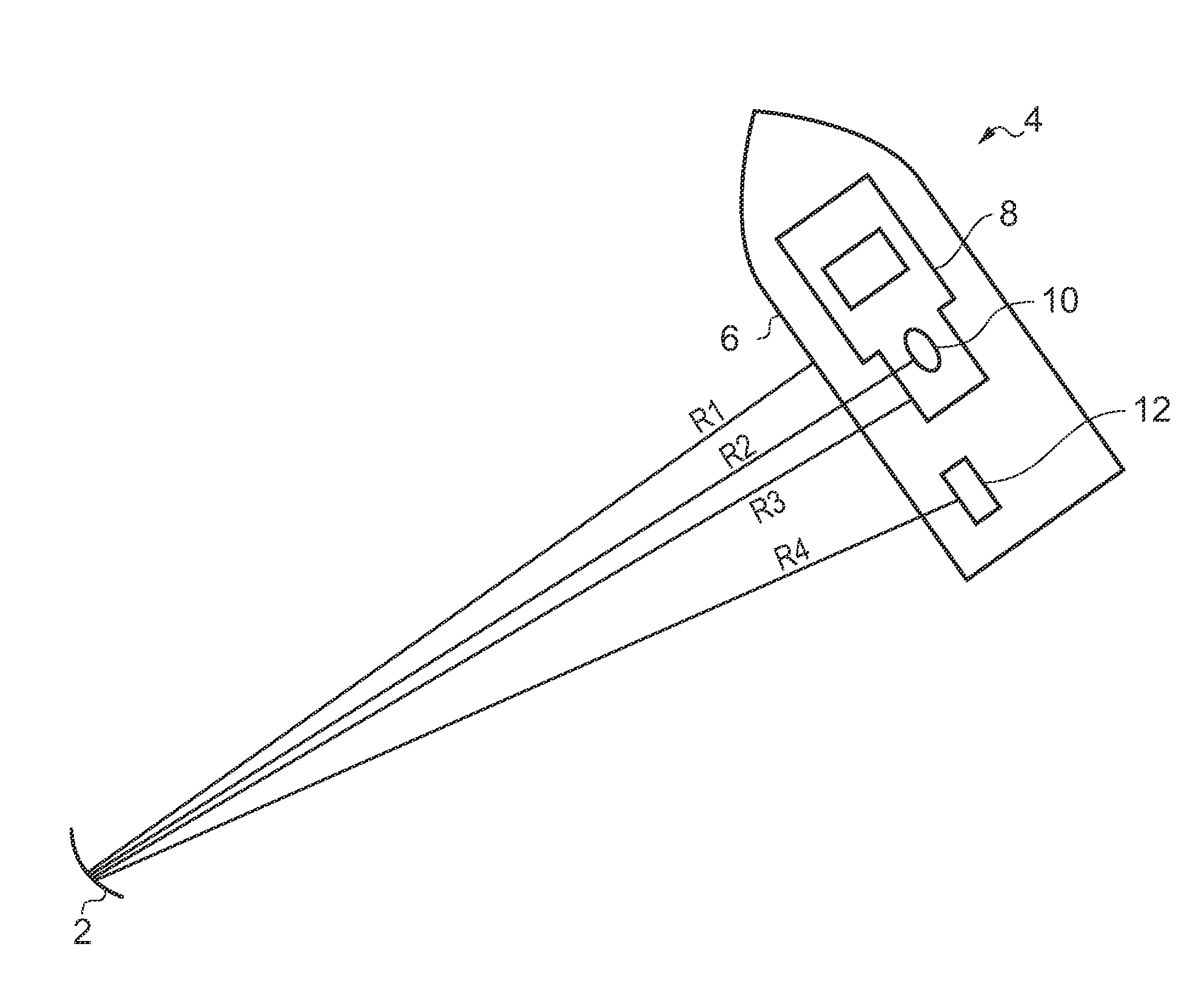
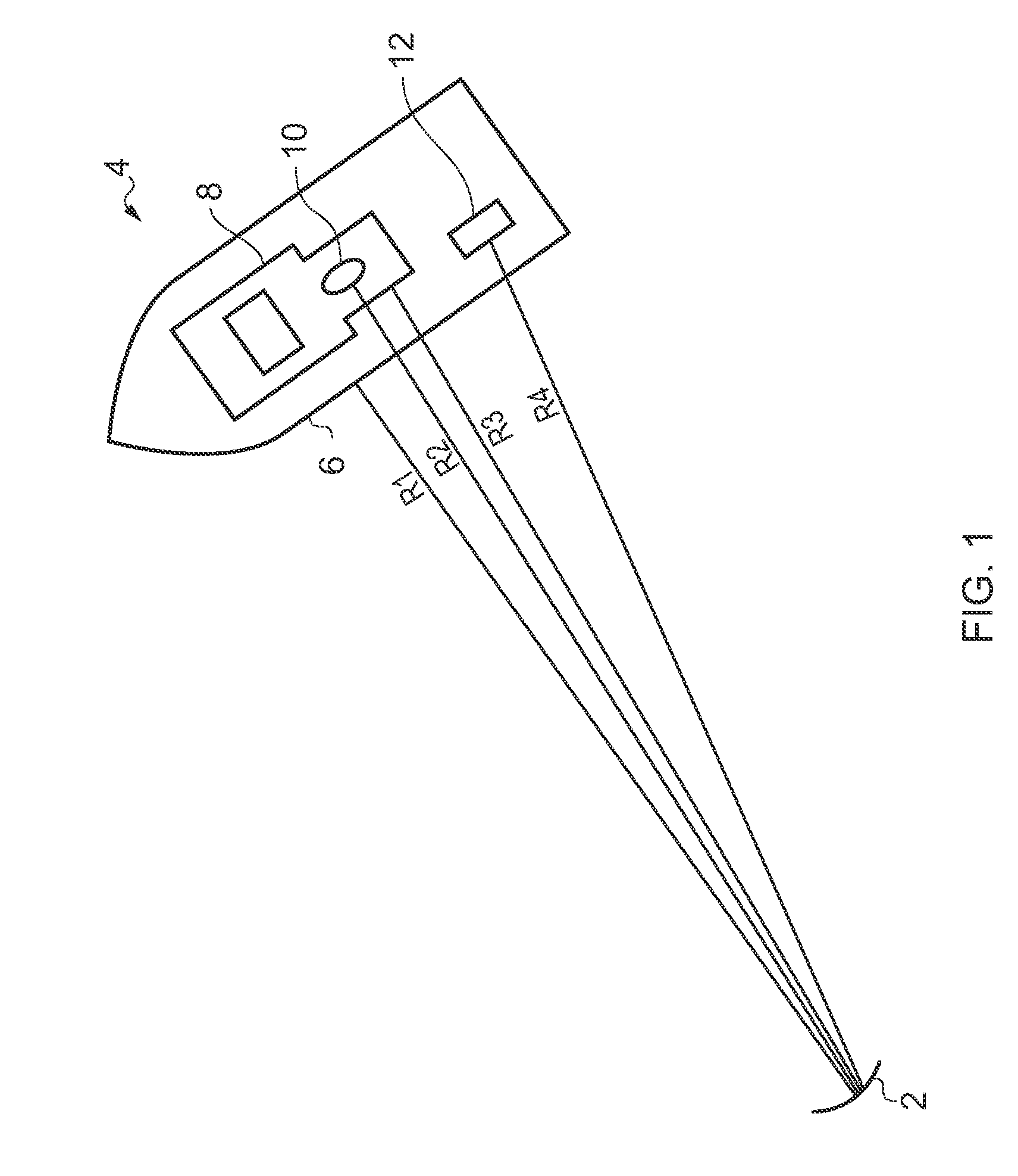
[0030]As noted hereinbefore, it can be difficult to obtain a very precise radar range to a complex target. FIG. 1 illustrates a situation where a radar, schematically represented by a parabolic dish 2 (although no inference should be taken from this as the invention is equally suitable for use with arrays of antennas operable to form beam steered arrays) which transmits a radar signal that illuminates a complex target 4, such as a large ship. The ship has a hull 6, a superstructure 8, a funnel 10 and an item of cargo 12. Each of these items may give a radar return, and as shown each reflecting item has a slightly different distance R1 to R4 respectively from the radar 2.

[0031]This is not a problem if one merely wishes to know that the ship is there and to get a rough distance to it, e.g. 1.5 nautical miles (1 nautical mile=1854 m).

[0032]However, some navigation, such as pipe laying and oil rig positioning requires the distance between objects to be measured to around 1 metre or less...


PUM


Abstract

An active radar target comprising a plurality of receive antennas and a plurality of transmit antennas arrangeable into pairs of antennas with at least one antenna in a pair being at a different height to at least one antenna in a different pair of antennas.

Description

CROSS REFERENCE TO RELATED APPLICATION[0001]This application claims priority to and the benefit of United Kingdom Patent Application No. GB1004995.5, filed Mar. 25, 2010, the entire disclosure of which is incorporated herein by reference in its entirety.FIELD OF THE INVENTION[0002]The present invention relates to an active radar target with height diversityBACKGROUND TO THE INVENTION[0003]Radar can be used to measure range and direction to a reflective object, which is often referred to as a “target”. However, a return may be achieved from all possible reflecting surfaces, which in the case of a large structure such as a ship or oil rig can give a large return signal, of extended angular range and a range of distances. This is generally acceptable for standard collision avoidance applications.[0004]However such diverse returns of the radar signal are not useful if it is desired to use radar to measure distance to a target, such as a vessel position relative to an oil rig, to a few m...

Claims


Application Information

Patent Timeline
29 Sep 2011
Publication
US20110234445A1
IPC
G01S13/74; G01S13/937
CPC
G01S3/14; G01S5/0247; G01S13/9307; G01S13/825; G01S7/025; G01S13/937; G01S13/767; H01Q1/22
Inventors
PATRICK, DAVID E.