
Super resolution optofluidic microscopes for 2d and 3D imaging

a technology of optofluidic microscope and optical microscope, which is applied in the field of super resolution optofluidic microscope, can solve the problems of limited image resolution in many conventional ofms, bulky optics of conventional optical microscopes, and high cost and miniaturization difficulties, and achieve high resolution and resolution

Active Publication Date: 2011-09-29
CALIFORNIA INST OF TECH
View PDF62 Cites 83 Cited by
  • Summary
  • Abstract
  • Description
  • Claims
  • Application Information

AI Technical Summary

Benefits of technology

[0036]Embodiments of the invention provide one or more technical advantages. A general advantage is that the SROFM uses a high sampling rate in the time domain (e.g., subpixel sampling rate) to offset the sub-Nyquist rate sampling in the spatial domain of the projection images, combining work done in super resolution imaging with optofluidic microscopy to provide a simple, low cost, high throughput microscopy device with significant resolution enhancement. A more specific advantage is that the SROFM of embodiments can be easily miniaturized. The SROFM can be easily miniaturized since it does not require bulky optics, motion controller or actuator needed in other microscanning schemes, or an on-board illumination source. Also, most of the SROFM can be in the form of a microfluidic chip. A miniaturized SROFM can provide a compact, inexpensive, and portable imaging system that may fulfill many needs in biological research, point-of-care analysis and field diagnostics. A miniaturized SROFM could also bring affordable healthcare diagnostics to less developed populations in rural settings, where it is too costly to deploy expensive conventional microscopes and skilled technicians. Another advantage is the elimination of the aperture array from the conventional OFM design. The SROFM eliminates the need of having an aperture array, which can simplify fabrication of the SROMFM and thus, reduce cost. Another advantage is that the SROFM has microfluidic flow of a fluid specimen across the light detector which allows for manipulation of the objects being imaged in subpixel shifts, and eliminates the need for a precision scanning setup needed in other super resolution devices. Another advantage is that the SROFM takes snapshot frames with a two-dimensional array over subpixel shifts. Many frames can be acquired over a short distance so that an HR image can be acquired without having the object pass over the entire array. Thus, acquisition time is reduced, which can improve throughput rates. Reducing acquisition time may also reduce exposure of the object being imaged to light, which can reduce the risk of damaging the object. Other advantages are provided in Section IIB.

Problems solved by technology

Conventional optical microscopes have bulky optics, and have proven to be expensive and difficult to miniaturize.
Also, image resolution in many conventional OFMs was limited.

Method used


Image

  • Super resolution optofluidic microscopes for 2d and 3D imaging
  • Super resolution optofluidic microscopes for 2d and 3D imaging
  • Super resolution optofluidic microscopes for 2d and 3D imaging

Examples


Embodiment Construction

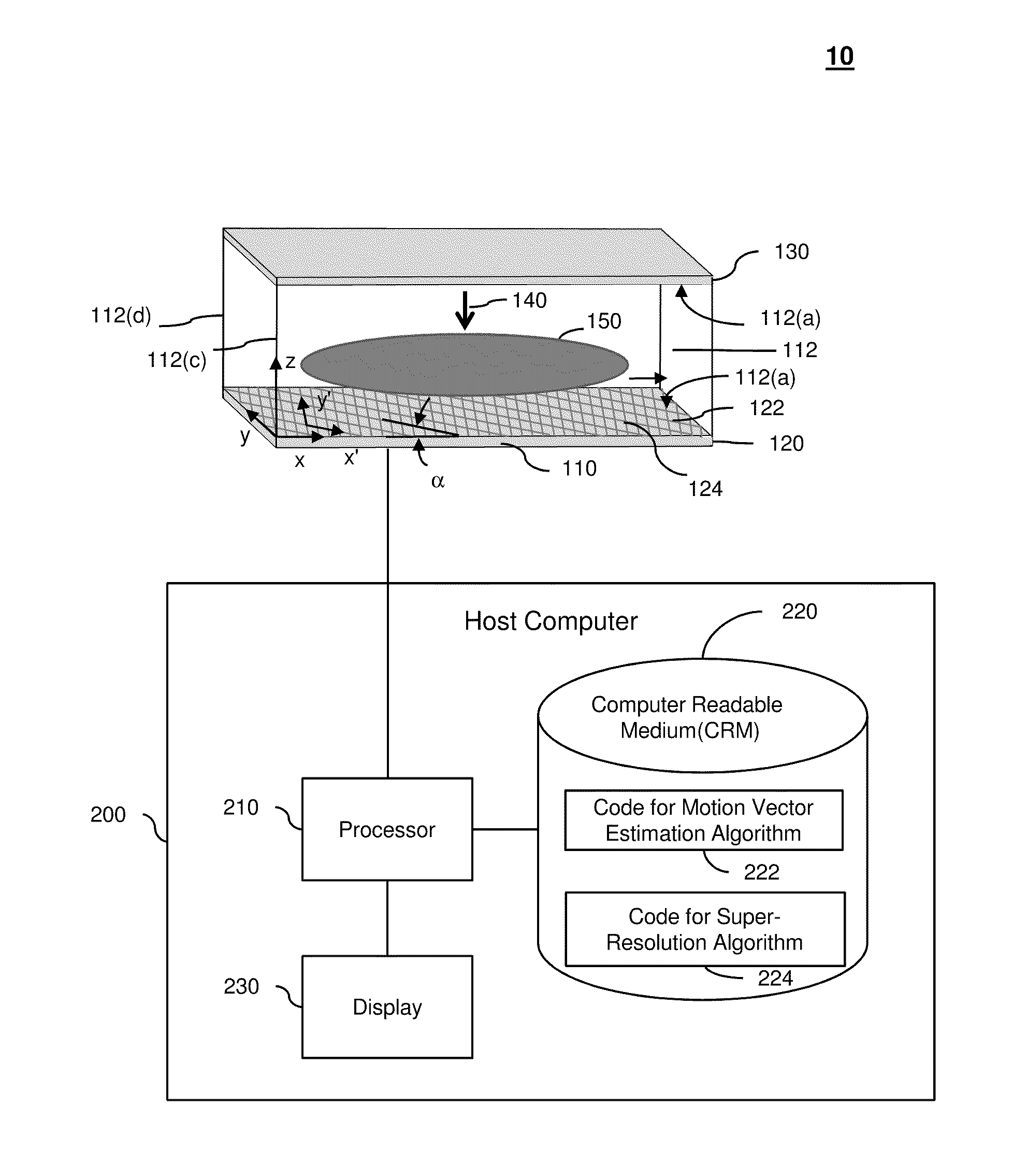
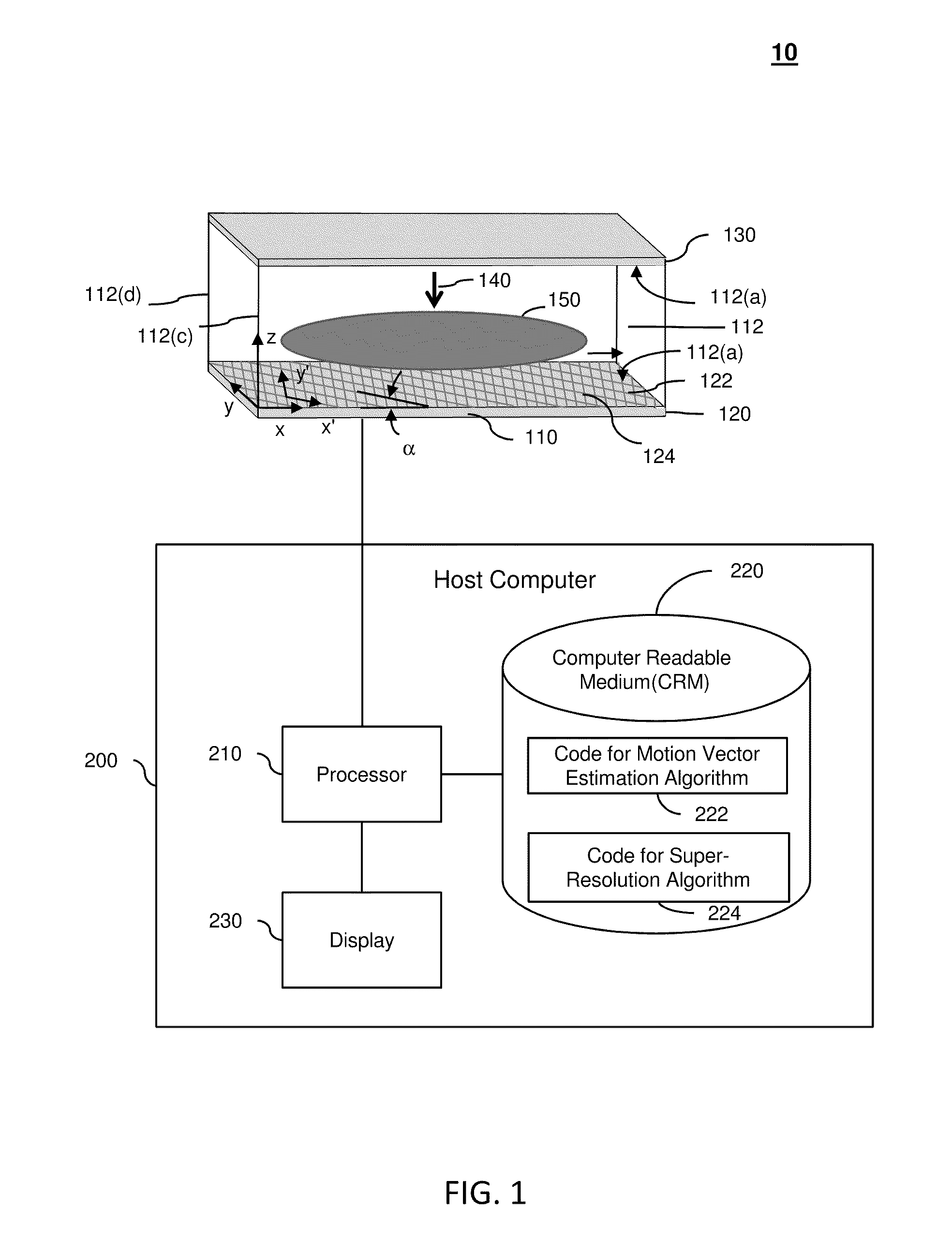
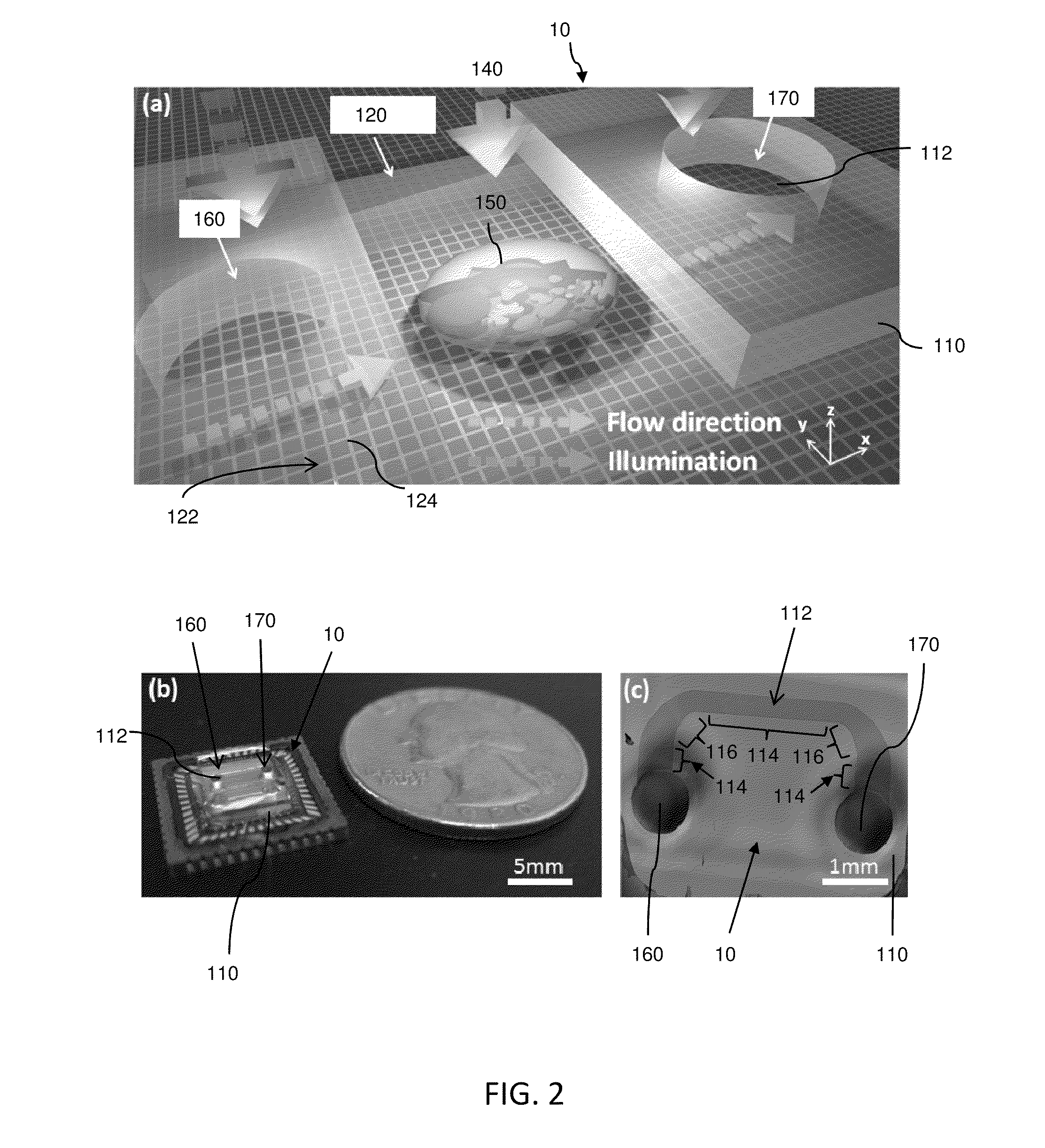
[0034]Embodiments of the present invention will be described below with reference to the accompanying drawings. Some embodiments include a SROFM have a body (e.g., microfluidic chip) defining a fluid channel and a light detector with a two-dimensional array of light detecting elements (e.g., CMOS sensor array). The light detector samples light data at a subpixel sampling rate to capture a sequence of subpixel-shifted snapshot projections (frames) as the object moves through the fluid channel. The processor determines the motion vector of the object. Then, the processor uses a super resolution algorithm (SR algorithm) to reconstruct a super-resolution (SR) two-dimensional image of an object from the sequence of subpixel-shifted frames and the motion vector. The processor can also determine a SR, three-dimensional image of the object by combining multiple reconstructed HR images from different incidence angles (views) using computed tomography.

[0035]The subpixel shifts of the object b...


PUM


Abstract

A super resolution optofluidic microscope device comprises a body defining a fluid channel having a longitudinal axis and includes a surface layer proximal the fluid channel. The surface layer has a two-dimensional light detector array configured to receive light passing through the fluid channel and sample a sequence of subpixel shifted projection frames as an object moves through the fluid channel. The super resolution optofluidic microscope device further comprises a processor in electronic communication with the two-dimensional light detector array. The processor is configured to generate a high resolution image of the object using a super resolution algorithm, and based on the sequence of subpixel shifted projection frames and a motion vector of the object.

Description

CROSS-REFERENCES TO RELATED APPLICATIONS[0001]This is a non-provisional application of, and claims priority to, U.S. Provisional Patent Application No. 61 / 316,762 entitled “Super Resolution Optofluidic Microscope for 2D and 3D Imaging” filed on Mar. 23, 2010. That provisional application is hereby incorporated by reference in its entirety for all purposes.[0002]This non-provisional application is related to the following co-pending and commonly-assigned patent application, which is hereby incorporated by reference in its entirety for all purposes:[0003]U.S. patent application Ser. No. 12 / 398,050 entitled “Optofluidic Microscope Device with Photosensor Array” filed on Mar. 4, 2009.BACKGROUND OF THE INVENTION[0004]Embodiments of the present invention generally relate to optofluidic microscopes devices (OFMs) and OFM systems. More specifically, certain embodiments relate to super resolution optofluidic microscope (SROFMs) for subpixel resolution, two-dimensional and three-dimensional i...

Claims


Application Information

Patent Timeline
Patent Type & Authority Applications(United States)
IPC IPC(8): H04N13/02H04N7/18H04N25/48
CPCG02B21/36H04N5/349G06T3/4053G02B21/0008H04N25/48G01N15/1484G01N15/147
Inventor ZHENG, GUOANYANG, CHANGHUEIYANG, SAMUELLEE, SEUNG AH
Owner CALIFORNIA INST OF TECH
Learn More