Retinal imaging system for the mouse or rat or other small animals

a retinal imaging and mouse eye technology, applied in the field of retinal imaging systems for mouse or rat or other small animals, can solve the problems of difficult image capture, difficult to achieve image capture, and difficult to achieve image quality

Active Publication Date: 2011-09-29
UNIV OF MIAMI
View PDF6 Cites 46 Cited by
  • Summary
  • Abstract
  • Description
  • Claims
  • Application Information

AI Technical Summary

Benefits of technology

[0007]The present invention advantageously provides for a small animal imaging system. The system includes a base element and a camera coupled to the base element the camera being sized to image the eye of a small animal. A light-emitting diode is also included and coupled to the base element. An OCT imaging apparatus is also included coupled to the base element. An X-Y scanner is also included coupled to the base element in communication with the OCT imaging apparatus.
[0008]In another embodiment, the method includes providing an OCT imaging apparatus and a camera sized to image the fundus of a small animal. The camera is optically aligned with the fundus of a small animal. A desired area of the fundus is then visualized for OCT imaging. The desired area of the fundus is then illuminated with light from a light-emitting diode. An image of the desired area of the fundus is then acquired with the camera and then an OCT image is acquired of the desired area.
[0009]In yet another embodiment, the system includes a base element and a camera coupled to the base element, the camera being sized to image the eye of a small animal. An OCT imaging apparatus is included and coupled to the base element. A light-emitting diode is included and also coupled to the base element. A first illumination lens is also included coupled to the base element proximate the light-emitting diode. A reflection mirror coupled to the base element is included proximate the first illumination lens, the reflection mirror defining an aperture app

Problems solved by technology

Traditional approaches to imaging the interior portion of the mouse eye, known as the fundus, have proven to be tedious.
Another alternative was to use two operators, one to hold the mouse and another to operate the camera, but this technique often produced inferior quality images.
However, there are several challenges with OCT in accurately and effectively imaging the interior surface of the fundus.
For example, the length of a mouse eye is approximately ⅛ the size of a human eye, making image capture more difficult.
Additio

Method used


Image

  • Retinal imaging system for the mouse or rat or other small animals
  • Retinal imaging system for the mouse or rat or other small animals
  • Retinal imaging system for the mouse or rat or other small animals

Examples


Embodiment Construction

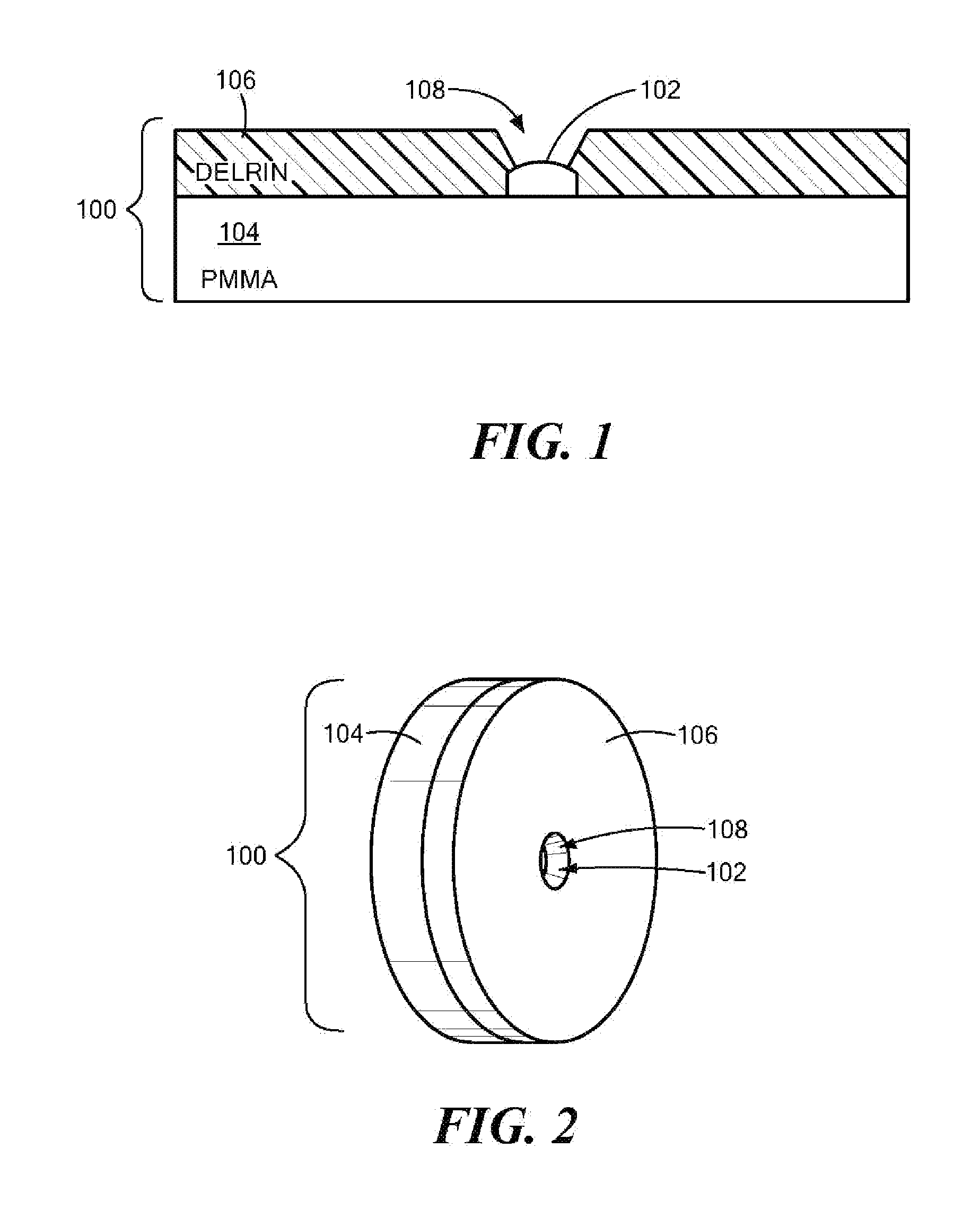
[0017]Referring now to the figures in which like reference designators refer to like elements, there is shown in FIG. 1 a cross-sectional view of a model mouse eye used to calibrate an OCT imaging system in accordance with the principles of the present invention referred to generally as “100.” The model eye 100 may comprise a plano-convex lens 102 with an optical power matching the optical power of the mouse eye (approximately 560 D). The plano-convex lens 102 may be approximately 2.5 mm in diameter. The model eye 100 may further include a Polymethyl methacrylate (PMMA) disc 104, or other similar material, placed in contact with the posterior surface of the plano-convex lens 102. The PMMA disc 104 may be approximately 25.4 mm in length, or any length, and have a height of approximately 3.72 mm, or any height. The posterior surface of the PMMA disc 104 may be located coincident with the focal plane of the plano-convex lens 102 (seen in FIG. 3). A black, or similarly colored disc 106,...


PUM


Abstract

A small animal imaging system comprising a base element and a camera coupled to the base element, the camera being sized to image the eye of a small animal. A light-emitting diode is also included coupled to the base element. An OCT imaging apparatus is also included coupled to the base element. An X-Y scanner is also included coupled to the base element in communication with the OCT imaging apparatus.

Description

FIELD OF THE INVENTION[0001]The present invention relates to a method and system for acquiring fundus and Optical Coherence Tomography (OCT) retinal or corneal images of mice, or other small animals, during examination or screening.BACKGROUND OF THE INVENTION[0002]Mice have become the primary model for the study of ocular diseases in humans. Because mice and humans share about 95% of their genome, a given gene in a mouse will likely have a homologous chromosomal segment in humans. Moreover, using mice for genetic research is advantageous because, for example, genetically identical mice can be inbred, disease progression in mice is more rapid due to their short life span, and mice are readily available for examination. Because of these advantages, mouse models are expected to play a vital role in the development of new pharmaceutical therapies for glaucoma, retinal degeneration, and retinal vascular diseases.[0003]In vivo quantitative and qualitative assessment of retinal morphology ...

Claims


Application Information

Patent Timeline
IPC IPC(8): A61B3/14A61B3/12
CPCA61B3/102A61F2009/00863A61F9/008A61B2019/5234A61B2090/3735
Inventor KOCAOGLU, OMERUHLHORN, STEPHENHERNANDEZ, ELEUTPORCIATTI, VITTORIOPAREL, JEAN-MARIEMANNS, FABRICE
Owner UNIV OF MIAMI
Why Eureka
Try Eureka