Physical information acquisition device, solid-state imaging device and physical information acquisition method

Inactive Publication Date: 2011-09-29
SONY CORP
View PDF8 Cites 71 Cited by
  • Summary
  • Abstract
  • Description
  • Claims
  • Application Information

AI Technical Summary

Benefits of technology

[0016]As a countermeasure, an optical member is preferably provided in the imaging optical path that has a narrow band-pass characteristic centered around the specific wavelength. This allows for detection of only the specific wavelength component, thus keeping the detection section unaffected even in the event of a high light intensity of the normal light source.
[0017]That is, according to an embodiment of the present invention, there is a solid-state imaging device including a detection section adapted to detect a component emitted from an electromagnetic wave output section adapted to generate electromagnetic wave at a wavelength equivalent to a specific wavelength when, for a first wavelength range of electromagnetic wave, a wavelength where electromagnetic wave energy is lower than at other wavelengths is determined to be the specific wavelength, the component reflected by an object. An optical member having a band-pass characteristic centered around the specific wavelength is provided in the imaging optical path. Further, there is a physical information acquisition method comprising the steps of irradiating an object with electromagnetic wave at a wavelength equivalent to a specific wavelength when, for a first wavelength range of electromagnetic wave, a wavelength where electromagnetic wave energy is lower than at other wavelengths is determined to be the specific wavelength, detecting electromagnet

Problems solved by technology

In the existing arrangement, however, light from the normal light source disturbs light from the different light source, making it occasionally impossible to acquire correct information.
Typically, disturbance noise caused by solar light is a serious prob

Method used


Image

  • Physical information acquisition device, solid-state imaging device and physical information acquisition method
  • Physical information acquisition device, solid-state imaging device and physical information acquisition method
  • Physical information acquisition device, solid-state imaging device and physical information acquisition method

Examples


first embodiment (

3. First embodiment (acquisition of high-sensitivity image, acquisition of infrared image, distance measurement)

4. Second embodiment

[0039]First example: Transmission of only a given specific wavelength component in the infrared range

[0040]Second example: Transmission of only a given specific wavelength component in the infrared range and visible light

[0041]Third example: Transmission of only absorbed solar wavelength components in the infrared range (infrared band-pass filters)

[0042]Fourth example: Transmission of only absorbed solar wavelength components in the infrared range and visible light

[0043](Visible and Infrared Band-Pass Filters)

[0044]Fifth example: “Second or fourth example” and color imaging (with on-chip infrared filter)

[0045]Sixth example: “Second or fourth example” and color imaging (without on-chip infrared filter)

[0046]Seventh example: Infrared cutoff filters for the visible pixels, on-chip filters for the infrared light pixel

[0047]Eighth example: Infrared cutoff fi...

first embodiment

[0119]FIG. 5 is a diagram describing an image signal processing section 340. The image signal processing section 340 includes a sensitivity enhancement correction processing section 341. The same section 341 images the subject Z with a different color and sensitivity level for each pixel according to the arrangement pattern of the color filters C1 to C4 (mosaic pattern) and converts a color / sensitivity mosaic image having colors and sensitivity levels in a mosaic pattern into an image in which each pixel has all color components and a uniform sensitivity level.

[0120]The sensitivity enhancement correction processing section 341 obtains a signal representing the amount of photometry (measured amount) based on unit signals, one for each wavelength, detected by the second detection section adapted to detect signals via the color filters C2 to C4. The same section 341 uses this signal representing the amount of photometry and the high-sensitivity signals of the respective color component...

first example

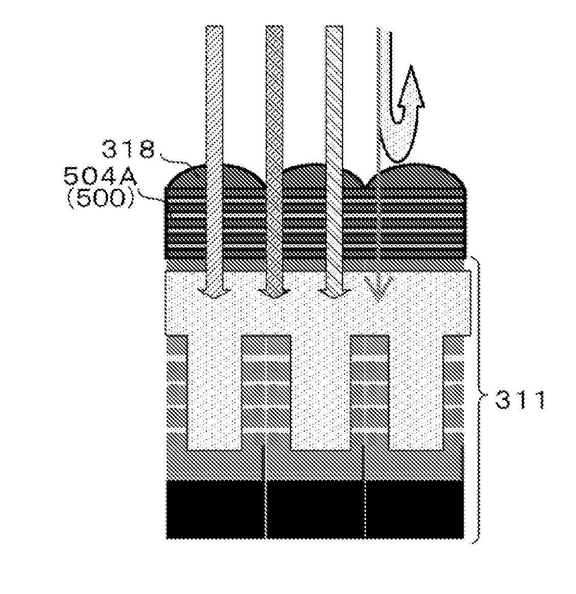
[0144]FIGS. 6A to 6D are diagrams illustrating a first example of a combination of a light source (light at a specific wavelength), optical filter section and imaging device structure.

[0145]The first example is characterized in that a light source (light-emitting section 322) is used that emits light containing one or more specific wavelength components in the infrared range, and that an optical band-pass filter 502 is provided in the photoreception optical path on the photoreception side as the optical filter section 500 to remove most of the wavelengths other than the specific wavelength. In the imaging optical system on the photoreception side, the special optical band-pass filter 502 is provided to transmit only a specific band of wavelengths of all the light emitted from the light source and cuts off all other infrared light and visible light. In order to reduce noise components of solar light, the optical band-pass filter 502 does not have to transmit wavelengths in the infrar...


PUM


Abstract

Disclosed herein is a physical information acquisition device including an electromagnetic wave output section, a first detection section, and a signal processing section. The electromagnetic wave output section is adapted to generate electromagnetic wave at a wavelength equivalent to a specific wavelength when, for a first wavelength range of electromagnetic wave, a wavelength where electromagnetic wave energy is lower than at other wavelengths is determined to be the specific wavelength. The first detection section is adapted to detect electromagnetic wave at the specific wavelength. The signal processing section is adapted to perform signal processing based on detection information acquired from the first detection section.

Description

BACKGROUND OF THE INVENTION[0001]1. Field of the Invention[0002]The present invention relates to a physical information acquisition device, solid-state imaging device and physical information acquisition method.[0003]2. Description of the Related Art[0004]Arrangements are known such as using a light source (different light source or measurement light source) different from a normal light source such as the outdoor solar light and the indoor illumination light to irradiate an object with light at a predetermined wavelength from the different light source, thus detecting reflected light from the object and processing various signals based on detection information obtained from the detection (refer to Japanese Patent Laid-Open No. Hei 7-218232, Japanese Patent Laid-Open No. Hei 11-153408, Japanese Patent Laid-Open No. 2003-185412, Japanese Patent Laid-Open No. 2009-014459, JP-T-2009-524072, referred to as Patent Documents 1 to 5, respectively, hereinafter).[0005]For example, an active ...

Claims


Application Information

Patent Timeline
IPC IPC(8): G01C3/08G01J3/46G01J5/10H01L27/146
CPCH04N5/2354H04N9/045H04N5/332H04N5/33H04N23/74H04N23/11H04N25/131H04N25/133H04N25/135H01L27/14G01S17/32G01C3/06G01C3/08G01J3/46H04N23/12
Inventor IWASAKI, MASANORI
Owner SONY CORP
Why Eureka
Try Eureka