Power converter and power conditioner

a power converter and power conditioner technology, applied in the direction of dc-ac conversion without reversal, process and machine control, instruments, etc., can solve the problem of low power conversion efficiency of the power converter provided with the conventional power conditioner b>36/b>, and achieve the effect of reducing switching loss, reducing conduction loss, and reducing switching loss

Active Publication Date: 2011-09-29
ORMON CORP
View PDF9 Cites 12 Cited by
  • Summary
  • Abstract
  • Description
  • Claims
  • Application Information

AI Technical Summary

Benefits of technology

[0028]As a result, the switching loss can be decreased, and the element in which the conduction loss is reduced as the switch element can be selected. Additionally, the fourth means performs the PWM control to the voltage of the difference between the square-wave voltage string and the sine-wave voltage. Each of the square-wave voltage string and the sine-wave voltage alternately changes on the positive and negative sides. Therefore, the switching is performed at a voltage lower than that of the conventional PWM-control inverter, so that the switching loss can be reduced.
[0029]Thus, in the power conditioner of one or more embodiments of the invention, the power conversion efficiency can be improved compared with the conventional power conditioner.
[0030]Further, each of the measuring circuits measures the voltage between both ends of each of the first to and third capacitors, the control means performs ON / OFF control to each of the first to eighth switch elements based on the measured value of each measuring circuit, and the gain calibration means calibrates the gain of each measuring circuit that measures the voltage between both ends of each of the first to and third capacitors. Therefore, there is no error such that the measured value varies with respect to the identical voltage due to a variation of components constituting the measuring circuits, which allows a spike noise caused by the error to be prevented from being generated in the output voltage at a moment when the control means switches the turn-on and turn-off of the first to eighth switch element.

Problems solved by technology

Therefore, unfortunately the power converter provided with the conventional power conditioner 36 has low power conversion efficiency because a large switching loss is generated during power conversion of the power conditioner 36.

Method used


Image

  • Power converter and power conditioner
  • Power converter and power conditioner
  • Power converter and power conditioner

Examples


Embodiment Construction

[0054]Embodiments of the present invention will be described below with reference to the drawings. In embodiments of the invention, numerous specific details are set forth in order to provide a more thorough understanding of the invention. However, it will be apparent to one with ordinary skill in the art that the invention may be practiced without these specific details. In other instances, well-known features have not been described in detail to avoid obscuring the invention.

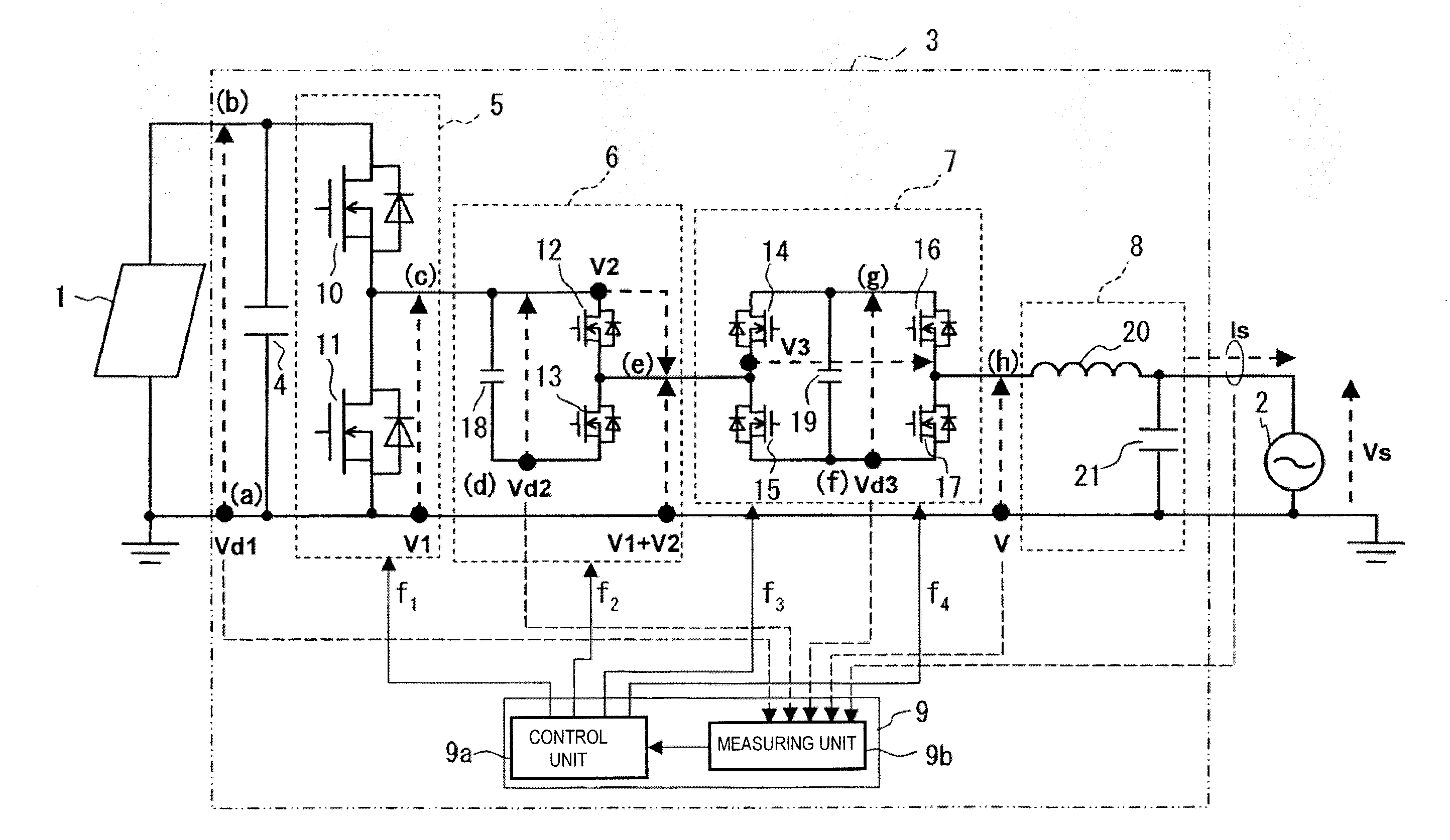
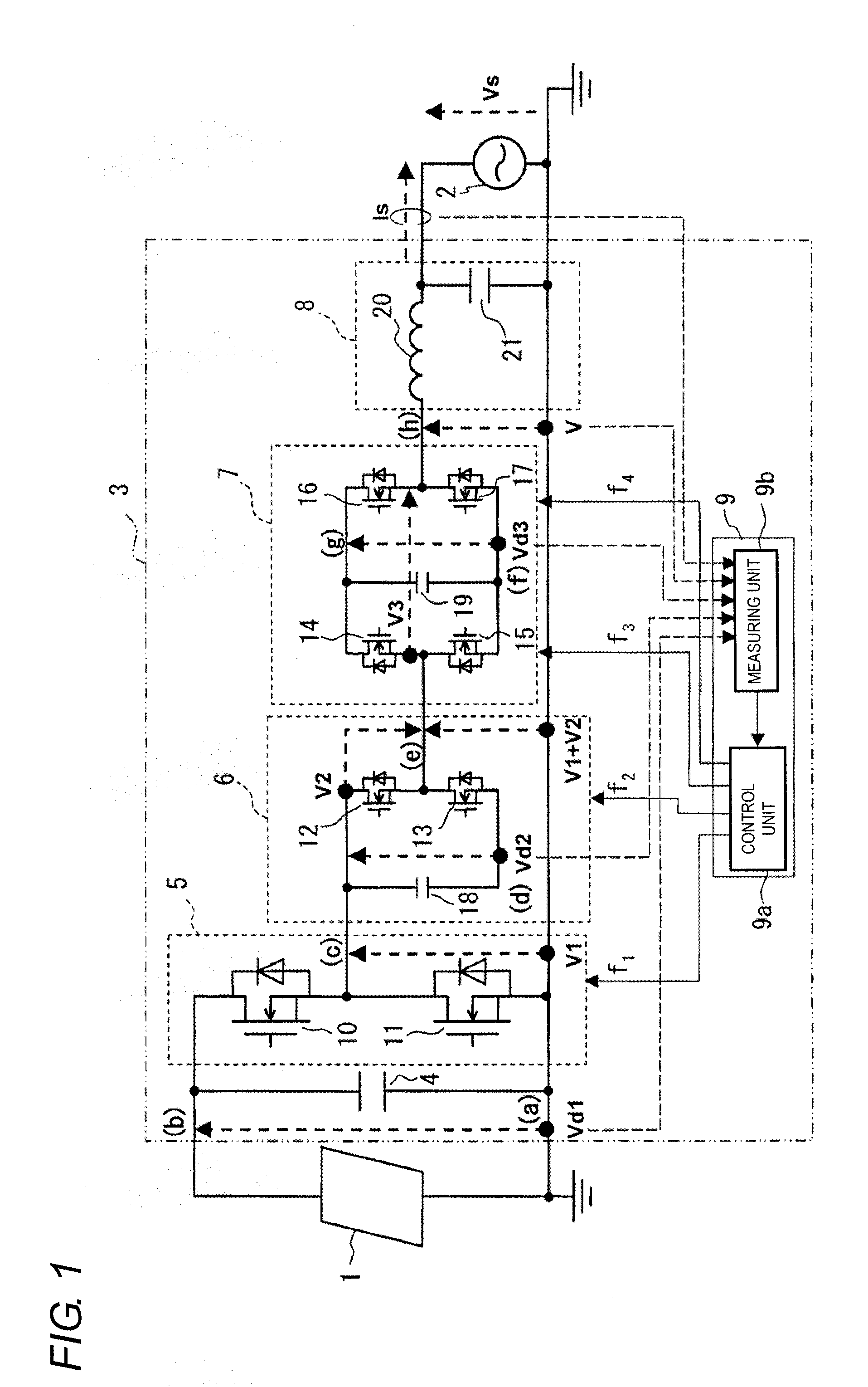
[0055]FIG. 1 is a configuration diagram of a photovoltaic power system according to one or more embodiments of the invention, and FIG. 1 illustrates a configuration of the single-phase two-wire system.

[0056]The photovoltaic power system of one or more embodiments includes a photovoltaic panel 1 and a power conditioner 3. The power conditioner 3 converts the DC power from the photovoltaic panel 1 into the AC power, and the power conditioner 3 is operated while interconnected to a commercial power source 2.

[0057...


PUM


Abstract

A power converter enhances conversion efficiency from DC power to AC power. A first chopper circuit chops DC voltage from a photovoltaic panel at a system frequency producing a first square-wave whose voltage level changes positively. A second chopper circuit chops the first square-wave at a frequency double the system frequency producing a second square-wave whose voltage level changes negatively and adds the first square-wave and the second square-wave to produce a third square-wave that changes positively and negatively in a sine-wave manner. A third chopper circuit charges and discharges by chopping the third square-wave at a third frequency fixed by timing according to a difference between the third square-wave and a sine-wave voltage. PWM control is performed on the charge and discharge outputs such that the difference is corrected, producing a sine-wave voltage that continuously changes positively and negatively. A spike noise of an output voltage is suppressed.

Description

BACKGROUND OF THE INVENTION[0001]1. Technical Field[0002]One or more embodiments of the present invention relate to a chopper type power converter that chops a DC power to convert the DC power into an AC power and a power conditioner provided therewith.[0003]One or more embodiments of the invention relate to a power converter that suitably converts the DC power generated by a DC power source such as a photovoltaic cell and a fuel cell into the AC power interconnected to a system and a power conditioner provided therewith.[0004]2. Related Art[0005]Recently, from the viewpoint of protection of a global environment, power generation systems, such as a photovoltaic cell and a fuel cell, which have a little influence on the environment are actively developed.[0006]In some power generation systems, a power conditioner converts a DC power from a DC power source such as the photovoltaic cell that generates the power into an AC power having a commercial frequency interconnected to a system. ...

Claims


Application Information

Patent Timeline
Patent Type & Authority Applications(United States)
IPC IPC(8): H02M7/5387
CPCH02M7/49H02M2001/0048Y02E10/56Y02B70/1491H02M2007/4835H02M1/42Y02B70/10H02M1/0048H02M7/4835H02M1/0095H02J3/38H02M3/28
Inventor MABUCHI, MASAOIMAMURA, KAZUYOSHIMIYAMOTO, MIOTAKAHASHI, KOHEI
Owner ORMON CORP
Why Eureka
Try Eureka