Method for fabricating the holographic grating

Inactive Publication Date: 2011-09-29
SUZHOU UNIV
View PDF2 Cites 3 Cited by
  • Summary
  • Abstract
  • Description
  • Claims
  • Application Information

AI Technical Summary

Benefits of technology

[0029]1. In this invention, a deformable mirror is placed into the holographic recording optical system. The deformable minor is inserted into the divergence optical beam, the size of the deformable mirror may be far less than the size of the recording beam. So the cost and difficulty in fabricating the deformable mirror are reduced greatly. Locating an interferometer in the normal direction of the deformable mirror can not only measure its surface shape, but also can allow the interferometer not to obstruct the holographic recording beams. The adjusting of the holographic interference field is implemented by the deformable minor. The aberration compensation to the substrate of grating is implemented by using the controllable wave-front of the holographic interference field and then

Problems solved by technology

In the previous art, it has been very difficult to fabricate the large scale substrate with low aberrations, especially for the substrate whose aperture is over 300 mm.
This leads to an overwhelming difficulty in fabricating holographic grating

Method used


Image

  • Method for fabricating the holographic grating
  • Method for fabricating the holographic grating
  • Method for fabricating the holographic grating

Examples


example 1

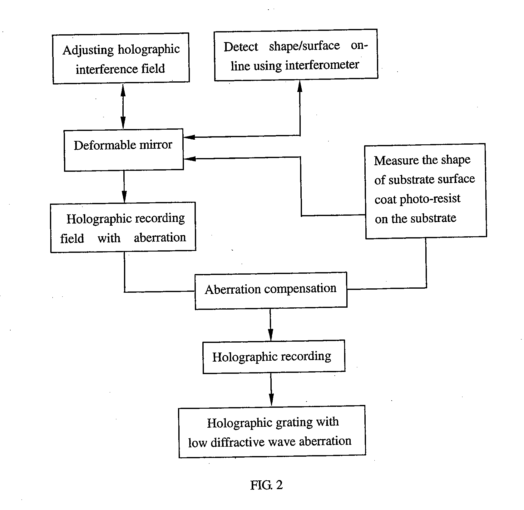
[0035]The comparison of the diffractive wave aberration between the two fabricating large scale grating methods, that is, ordinary holographic recording method and the method mentioned in this invention, is shown as follows.

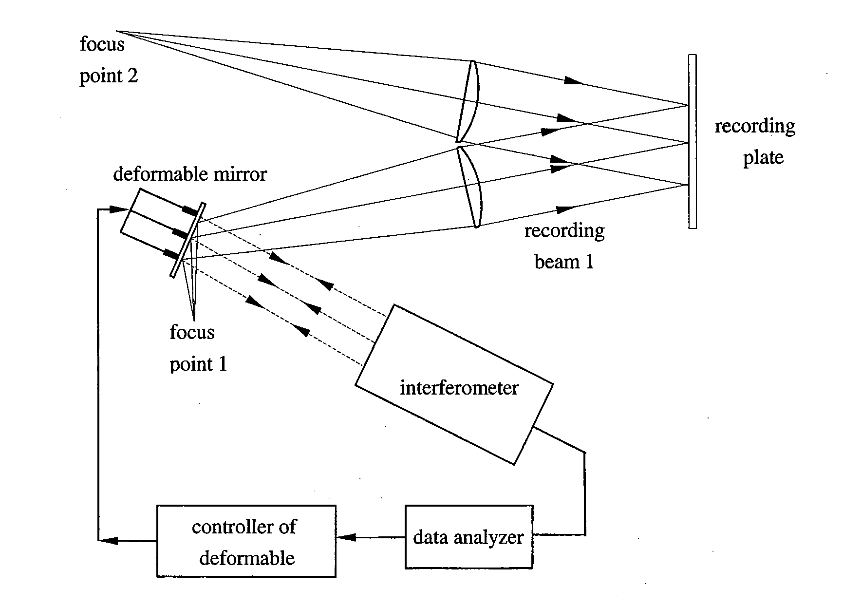
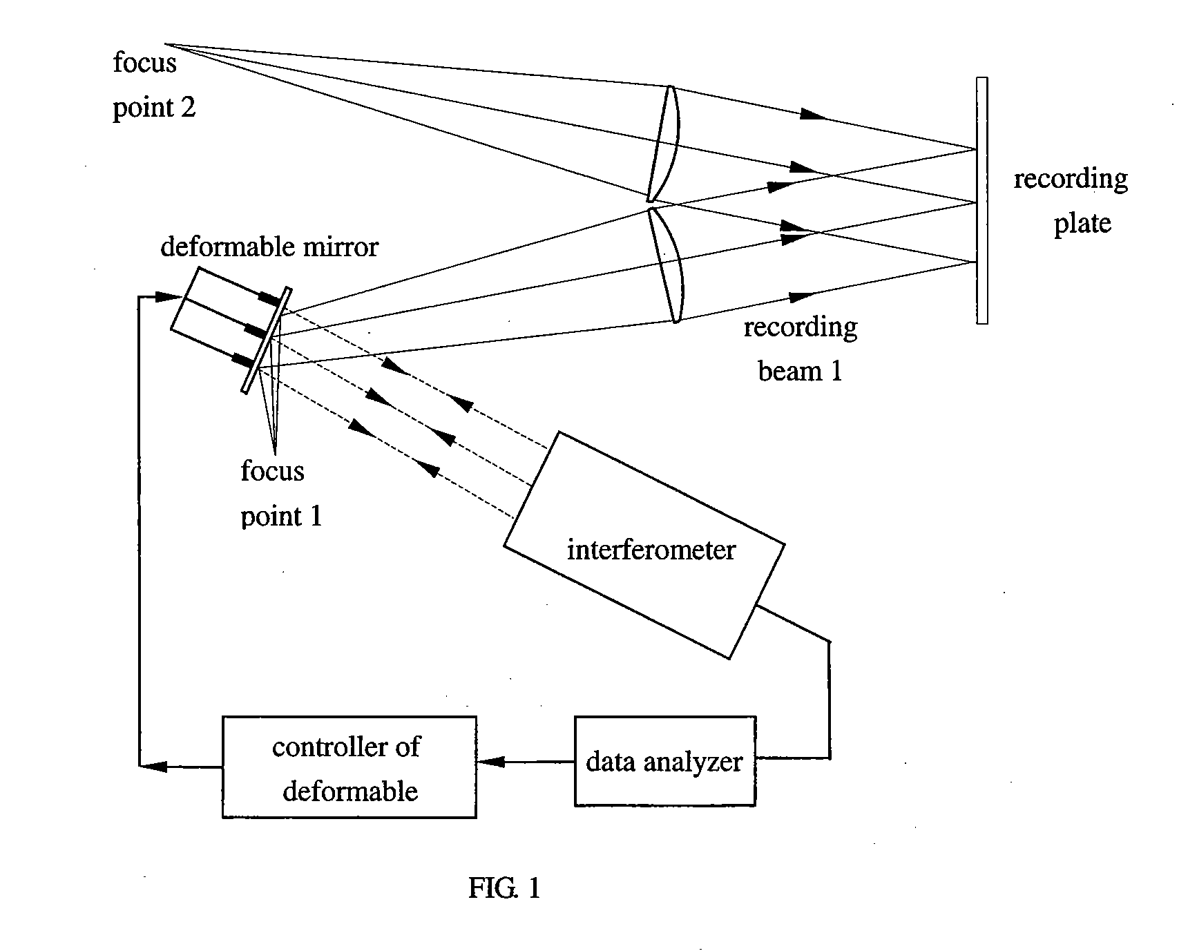
[0036]Assume the fabricating of a one dimension grating with a scale of 200 mm×400 mm and spatial frequency of 1740 lp / mm by an ordinary holographic recording method. The wavelength of two parallel recording beams is 413.1 nm. The incident angle of these two recording beams is 21°. Suppose that the aberration of these two recording beams is null and the surface shape of the substrate coated with photo-resist (i.e. recording plate) is 0.5λ. Here λ is the measuring wavelength and λ=632.8 nm. The recording plate is exposed and the holographic grating is recorded. When a parallel beam incidence this grating at the Littrow incident angle, the diffractive wave aberration of the grating is 0.84λ calculated by the formula of diffractive wave aberration of holographic gra...


PUM


Abstract

This invention discloses a method for fabricating a holographic grating with low diffractive wave aberrations on a substrate with aberrations. Forming a interference recording field from two coherent beams, where one is a parallel beam and the other is a beam whose wave-front can be controlled, recording the holographic field on the substrate with aberrations, fabricating the holographic grating with low diffractive wave aberrations, setting a deformable minor into one of the coherent recording beams, and controlling the shape of said deformable minor so as to obtain a compensated interference recording field. Expose the recoding plate under the holographic interference recording field which has been adjusted by the deformable minor to record the grating. After developing, the fabrication of holographic grating with low diffractive wave aberration is finished.

Description

CROSS-REFERENCES TO RELATED APPLICATIONS[0001]This application claims priority from Chinese Application No. 201010142320.2, filed Mar. 25, 2010 incorporated by reference in its entirety.[0002]This invention relates to a method for fabricating a diffractive element, and more particularly to a method for fabricating a low diffractive wave aberration holographic grating on a large scale substrate that contains aberrations.BACKGROUND[0003]A large scale plane diffractive grating with one dimension is a key element in some high technology projects such as a inertial confined fusion laser system. In order to meet the requirement of the high energy, the grating should be provided with large size and low diffractive aberration. The diffractive aberrations of the grating are related to the whole holographic optical recording system. It comprises of two parts. One is the holographic optical recording system, and the other is the substrate. The holographic optical recording system is used to pr...

Claims


Application Information

Patent Timeline
IPC IPC(8): G03F7/00
CPCG02B5/1857G02B5/32G03H2001/0439G03H1/04G02B26/0825
Inventor LI, CHAOMINGCHEN, XINRONGPAN, JUNHUAWU, JIANHONGHU, ZUYUAN
Owner SUZHOU UNIV
Why Eureka
Try Eureka