Polishing apparatus, polishing method and pressing member for pressing a polishing tool

a technology of polishing apparatus and pressing member, which is applied in the direction of grinding drive, grinding machine components, manufacturing tools, etc., can solve the problems of reducing yield, reducing the accuracy of polishing the top edge portion and the bottom edge portion by flat pressing surface, and forming roughened surfaces on the peripheral portion of the substrate. achieve the effect of accurately polishing the peripheral portion

Active Publication Date: 2011-09-29
EBARA CORP
View PDF16 Cites 28 Cited by
  • Summary
  • Abstract
  • Description
  • Claims
  • Application Information

AI Technical Summary

Benefits of technology

[0009]The present invention has been made in view of the above drawbacks. It is therefore an object of the present invention to provide a polishing apparatus capable of polishing a top edge portion and / or a bottom edge portion of a substrate accurately and uniformly. Further, another object of the present invention is to provide a polishing method using such a polishing apparatus and to provide a pressing member for pressing a polishing tool used in the polishing apparatus.
[0027]According to the present invention, the protrusion presses the polishing tool (e.g., polishing tape) against the peripheral portion of the substrate. Therefore, the polishing tool can accurately polish the peripheral portion without contacting regions other than the peripheral portion. Further, because the protrusion is curved along the circumferential direction of the substrate, the contact time between the substrate and the polishing tool is uniform over polishing region in its entirety. Therefore, it is possible to uniformly polish the entire polishing region including the inner edge of the peripheral portion of the substrate.

Problems solved by technology

Therefore, unwanted films and roughened surface are formed on a peripheral portion of the substrate which is not used for products.
Under such circumstances, the unwanted films remaining on the peripheral portion would be peeled off during various processes and could adhere to devices, causing lowered yield.
However, it is difficult to accurately polish the top edge portion and the bottom edge portion by the flat pressing surface.
In particular, when the polishing head is inclined such that the polishing tape makes an acute angle with a surface of the substrate, the devices may be damaged by the polishing tape.

Method used


Image

  • Polishing apparatus, polishing method and pressing member for pressing a polishing tool
  • Polishing apparatus, polishing method and pressing member for pressing a polishing tool
  • Polishing apparatus, polishing method and pressing member for pressing a polishing tool

Examples


Embodiment Construction

[0076]Embodiments of the present invention will be described below with reference to the drawings.

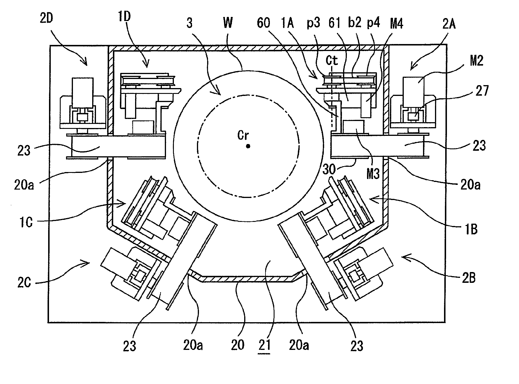
[0077]FIG. 3 is a plan view showing a polishing apparatus according to an embodiment of the present invention. FIG. 4 is a vertical cross-sectional view of the polishing apparatus shown in FIG. 3. As shown in FIG. 3 and FIG. 4, the polishing apparatus includes a rotary holding mechanism (a substrate holder) 3 configured to hold a substrate W (i.e., a workpiece to be polished) horizontally and to rotate the substrate W. The rotary holding mechanism 3 is located in the center of the polishing apparatus. FIG. 3 shows a state in which the rotary holding mechanism 3 holds the substrate W. This rotary holding mechanism 3 has a dish-shaped holding stage 4 configured to hold a rear surface of the substrate W by a vacuum suction, a hollow shaft 5 coupled to a central portion of the holding stage 4, and a motor M1 for rotating the hollow shaft 5. The substrate W is placed onto the holding stage 4...


PUM

PropertyMeasurementUnit
angleaaaaaaaaaa
widthaaaaaaaaaa
heightaaaaaaaaaa

Abstract

A polishing apparatus polishes a top edge portion and / or a bottom edge portion of a substrate accurately and uniformly. The polishing apparatus includes a rotary holding mechanism 3 configured to hold the substrate W horizontally and to rotate the substrate W; and at least one polishing head 30 disposed near the peripheral portion of the substrate. The polishing head 30 has at least one protrusion 51a, 51b extending along a circumferential direction of the substrate W, and the polishing head 30 is configured to press a polishing surface of a polishing tape 23 by the protrusion 51a, 51b against the peripheral portion of the substrate W from above or below.

Description

BACKGROUND OF THE INVENTION[0001]1. Field of the Invention[0002]The present invention relates to a polishing apparatus and a polishing method for polishing a substrate, such as a semiconductor wafer, and more particularly to a polishing apparatus and a polishing method for polishing a peripheral portion of a substrate using a strip-shaped polishing tool, such as a polishing tape. The present invention also relates to a pressing member for pressing the strip-shaped polishing tool against the peripheral portion of the substrate.[0003]2. Description of the Related Art[0004]From a viewpoint of improving yield in fabrication of semiconductor devices, management of surface conditions of a peripheral portion of a substrate has been attracting attention in recent years. In the fabrication process of the semiconductor devices, many materials are deposited on a silicon wafer to form a multilayer structure. Therefore, unwanted films and roughened surface are formed on a peripheral portion of t...

Claims


Application Information

Patent Timeline
Patent Type & Authority Applications(United States)
IPC IPC(8): B24B1/00B24B27/00
CPCB24B9/065B24B37/27B24B21/004B24B9/00B24B21/00H01L21/304
Inventor SEKI, MASAYAITO, KENYANAKANISHI, MASAYUKI
Owner EBARA CORP
Why Eureka
Try Eureka