Electronic endoscope system

a technology of endoscopy and endoscope, which is applied in the field of electronic endoscopy systems, can solve the problems of not being able to produce accurately aligned images and not being able to accurately align oxygen saturation levels, and achieve the effect of accurately obtaining the oxygen saturation level of blood vessels

Inactive Publication Date: 2011-09-29
FUJIFILM CORP
View PDF8 Cites 99 Cited by
  • Summary
  • Abstract
  • Description
  • Claims
  • Application Information

AI Technical Summary

Benefits of technology

[0010]The present invention has been made in view of the above problems and it is thus an object of the present invention is to accurately obtain an oxygen saturation level of a blood vessel, which is of great importance in diagnosis, by producing an oxygen saturation level image through alignment of a plurality of frame images that are frame-sequentially acquired using light of different wavelengths based on the position of blood vessels.
[0017]The present invention, provided both an alignment function based on a blood vessel position and an oxygen saturation level derivation function, permits accurately obtaining the oxygen saturation level of a blood vessel, which is of critical importance in diagnosis.

Problems solved by technology

However, the method described in JP 03-21186 A fails to correct color deviation, if any, and therefore does not enable production of an accurately aligned image.
In addition, the inventions described therein do not base the alignment on the position of blood vessels and, therefore, could not produce an accurately aligned oxygen saturation level image.

Method used


Image

  • Electronic endoscope system
  • Electronic endoscope system
  • Electronic endoscope system

Examples


first embodiment

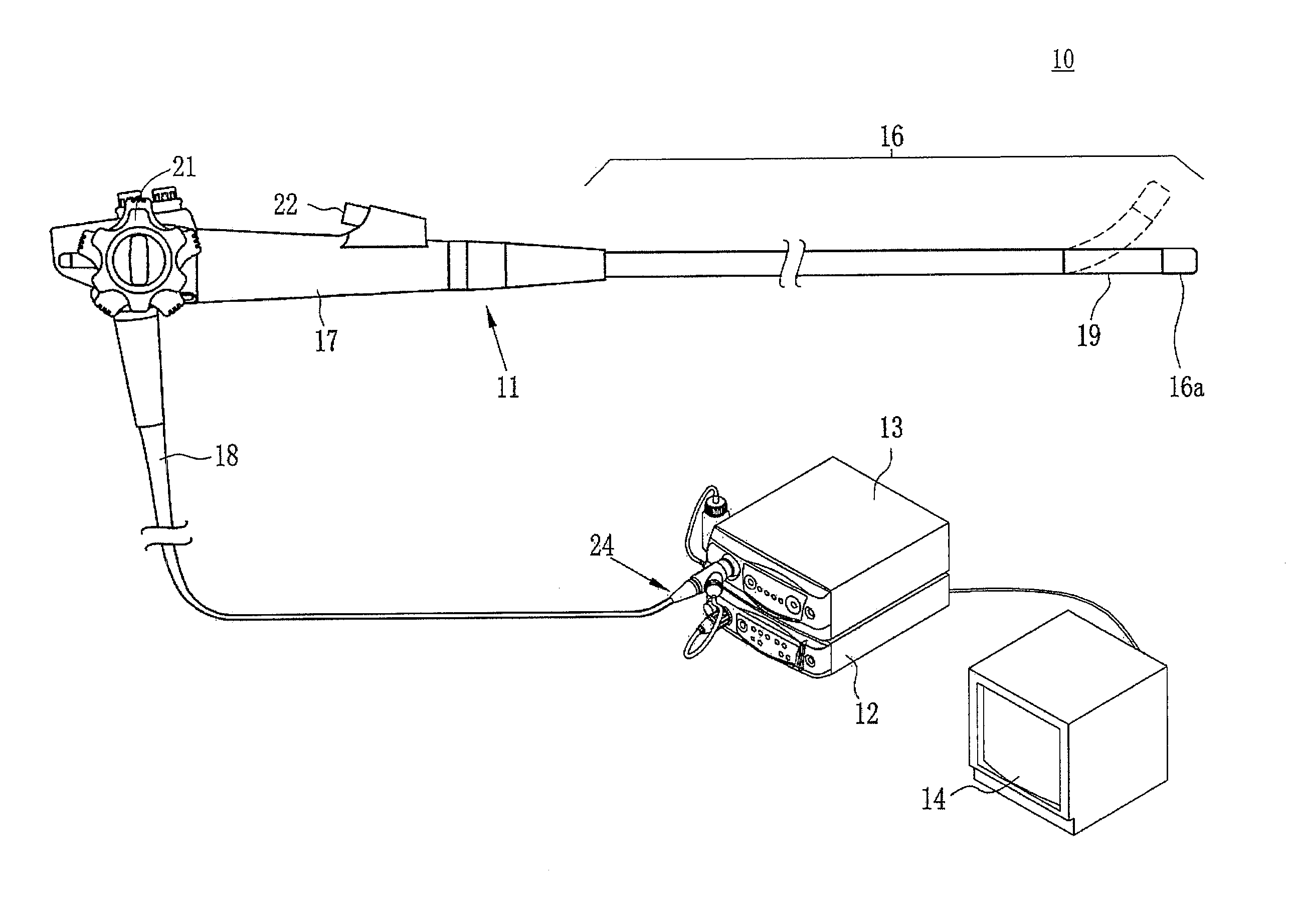
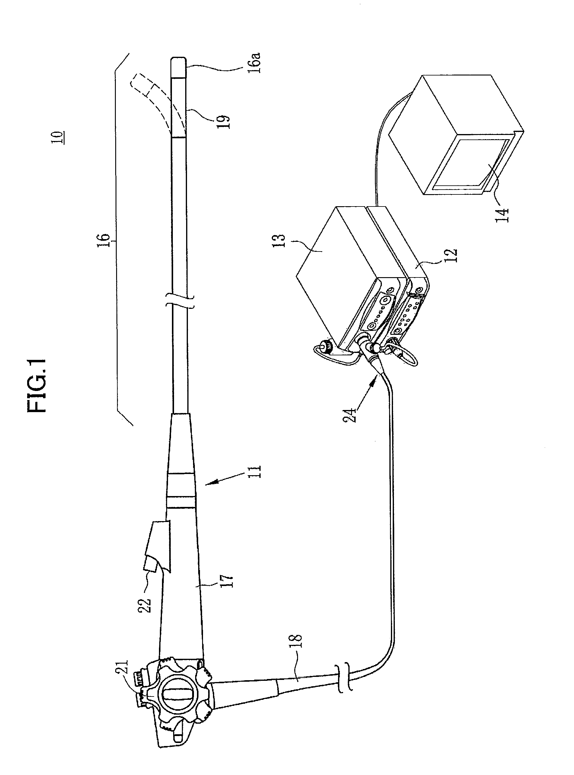
[0032]As illustrated in FIG. 1, an electronic endoscope system 10 according to the invention comprises an electronic endoscope 11 for imaging the inside of a subject's body cavity, a processor 12 for producing an image of a subject tissue in the body cavity based on a signal acquired by imaging, a light source device 13 for supplying light used to illuminate the inside of the body cavity, and a monitor (image display means) 14 for displaying the image of the inside of the body cavity. The electronic endoscope 11 comprises a flexible insertion section 16 that is inserted into a body cavity, an operating section 17 provided at the base of the insertion section 16, and a universal cord 18 for connecting the operating section 17 to the processor 12 and the light source device 13.

[0033]The insertion section 16 has a bending portion 19 at the tip thereof comprising connected bending pieces. The bending portion 19 bends up and down, left and right in response to the operation of an angle k...

second embodiment

[0096]the invention is provided with a narrowband light source producing narrowband light having a given wavelength in lieu of the broadband light source 30 such as a xenon light source.

[0097]The second embodiment differs from the first embodiment in the configuration of the light source 13, the blood vessel extraction processing by the blood vessel extraction means 65, and the alignment by the alignment means 66. The second embodiment share the other features with the first embodiment, and their descriptions therefore will not be repeated below.

[0098]As illustrated in FIG. 12, the light source device 13 comprises fourth to sixth narrowband light sources 33 to 35, a coupler 36, and a light source selector 37.

[0099]The fourth to the sixth narrowband light sources 33 to 35 are laser diodes or the like. The fourth narrowband light source 33 produces narrowband light having a wavelength limited to 400 nm+ / −10 nm, preferably 405 nm (referred to below as “fourth narrowband light N4”), the...

third embodiment

[0119]The light source selector 37 is connected to the controller 59 in the processor and turns on or off the broadband light source 90 and the fourth to the sixth narrowband light sources 33 to 35 according to an instruction by the controller 59. the broadband light source 90 and the fourth to the sixth narrowband light sources33 to 35 are sequentially turned on to perform imaging using the broadband light BB and the fourth to the sixth narrowband light N4 to N6.

[0120]Similarly to the first embodiment, the broadband light BB and the fourth narrowband light N4 to the sixth narrowband light N6 enter the CCD 44 of the endoscope 11 to obtain a broadband signal and a fourth narrowband imaging signal to a sixth narrowband imaging signal.

[0121]The CCD 44 comprises red (R) filters, green (G) filters, and blue (B) filters, which have spectral transmittances 52, 53, and 54, respectively as illustrated in FIG. 14. This embodiment differs from the second embodiment in that the light sources i...


PUM


Abstract

An electronic endoscope system includes a light source device for sequentially emitting kinds of light having different wavelength bands, an electronic endoscope for sequentially illuminating the kinds of light to a subject tissue containing blood vessels, receiving the kinds of reflected light, and outputting image data corresponding to the kinds of received light, an extractor for extracting positions of a blood vessel from each image data corresponding to the kinds of light, an aligner for aligning images corresponding to the image data based on the positions, an image producer for producing an oxygen saturation level image representing the distribution of the oxygen saturation level in the blood vessel from the image data of the aligned images, and an image monitor for displaying the oxygen saturation level image in simulated color.

Description

BACKGROUND OF INVENTION[0001]The present invention relates to an electronic endoscope system for acquiring information on a blood vessel from an image acquired by an electronic endoscope and producing an image from the acquired information.[0002]In recent years, a number of diagnoses and treatments using electronic endoscopes have been made in the field of medicine. A typical electronic endoscope is equipped with an elongated insertion section that is inserted into a subject's body cavity. The insertion section has therein incorporated an imager such as a COD at the tip thereof. The electronic endoscope is connected to a light source device, which emits light from the tip of the insertion section to illuminate the inside of a body cavity. With the inside of the body cavity illuminated by light, the subject tissue inside the body cavity is imaged by an imager provided at the tip of the insertion section. Images acquired by imaging undergoes various kinds of processing by a processor ...

Claims


Application Information

Patent Timeline
Patent Type & Authority Applications(United States)
IPC IPC(8): A61B1/04
CPCA61B1/00009A61B1/00045A61B1/0005A61B1/0638A61B1/063A61B5/0084A61B5/14551A61B5/489A61B1/0646A61B1/000094A61B1/0655
Inventor SAITO, TAKAAKI
Owner FUJIFILM CORP
Why Eureka
Try Eureka