Method and system for healthy home zoning control configured for efficient energy use and conservation of energy resources

a zoning control and healthy technology, applied in the field of solar energy application for home space conditioning and zoning control, can solve the problems of increasing the rate of warming, still certain limitations, and increasing sea levels, and achieves the effects of optimizing thermal energy distribution, convenient use, and efficient energy us

Inactive Publication Date: 2011-09-29
FTC SOLAR INC
View PDF5 Cites 40 Cited by
  • Summary
  • Abstract
  • Description
  • Claims
  • Application Information

AI Technical Summary

Benefits of technology

[0011]In a specific embodiment, the present invention provides an integrated healthy home system that optimizes the utilization thermal energy and eliminates any conflict with auxiliary thermal system. The system has a controller for at least a thermal energy transfer module within a building and one or more thermostats configured to communicate with the controller in a dedicate network for replicate an integrated zone control for multiple conditioned spatial zones of the building. Of course, there can be other variations, modifications, and alternatives.
[0016]Many benefits are achieved by way of the present invention over conventional techniques. For example, the present technique provides an easy to use process that relies upon an advanced solar energy based healthy home system integrated with conventional technologies such as solar PV modules, thermostat devices, air handler, air conditioning module and furnace, although other auxiliary thermal systems can also be used. Additionally, the system and method provide a coordinated control over the solar thermal energy utilization in home space conditioning application in a building structure with multiple spatial zones. It not only provides a process that is compatible with any updated solar thermal system without substantial modifications to equipment and processes but also provides optimized thermal energy distributions with efficient energy use and conservation of energy resources. Preferably, the invention provide a method that eliminates any conflict between operations of a solar thermal system and an auxiliary thermal system associated with energy transfer and space conditioning thermal loads.

Problems solved by technology

Obviously, our daily lives depend, for the most part, upon oil or other forms of fossil fuel, which are becoming scarce as it becomes depleted.
The increase in temperature is expected to cause extreme weather conditions and a drastic size reduction of the polar ice caps, which in turn will lead to higher sea levels and an increase in the rate of warming.
Ultimately, other effects include mass species extinctions, and possibly other uncertainties that may be detrimental to human beings.
Although solar panels have been used successful for certain applications, there are still certain limitations.
Solar cells are often costly.
Depending upon the geographic region, there are often financial subsidies from governmental entities for purchasing solar panels, which often cannot compete with the direct purchase of electricity from public power companies.
Additionally, most PV solar energy systems only utilize about 15% of the captured sun's energy.
Especially for the building structure including multiple spatial zones, due to variation in occupancy status and seasoning status associated with each spatial zone, energy cost of the conventional operation is very high and very inefficient.
In particular, there is no existing method to program the control setting for automatically adjusting building comfort band associated with each of the multiple zones for maximizing the solar thermal energy utilization before initiating an auxiliary thermal module for providing home heating, home cooling, and ventilation.

Method used


Image

  • Method and system for healthy home zoning control configured for efficient energy use and conservation of energy resources
  • Method and system for healthy home zoning control configured for efficient energy use and conservation of energy resources
  • Method and system for healthy home zoning control configured for efficient energy use and conservation of energy resources

Examples


Embodiment Construction

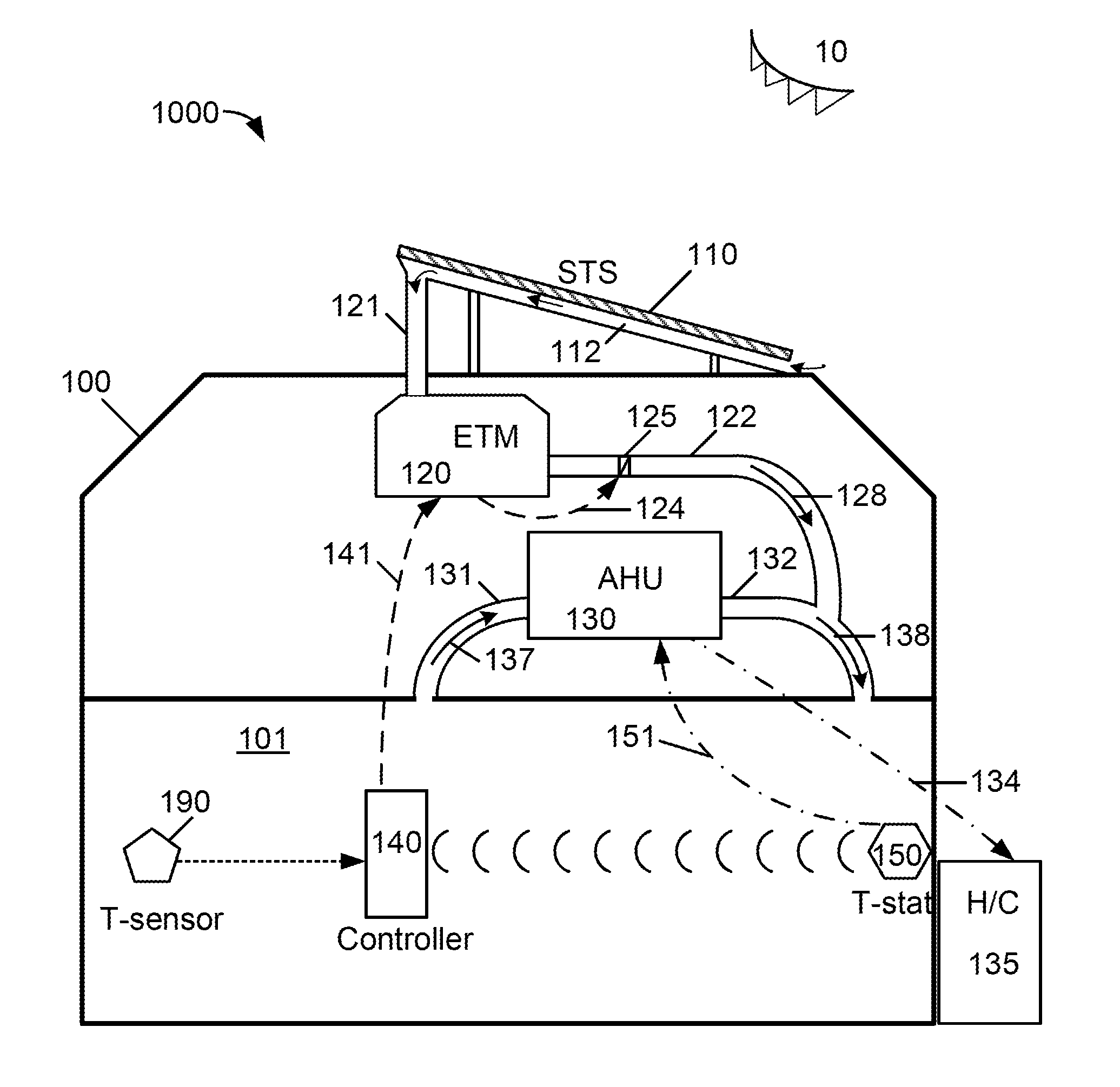
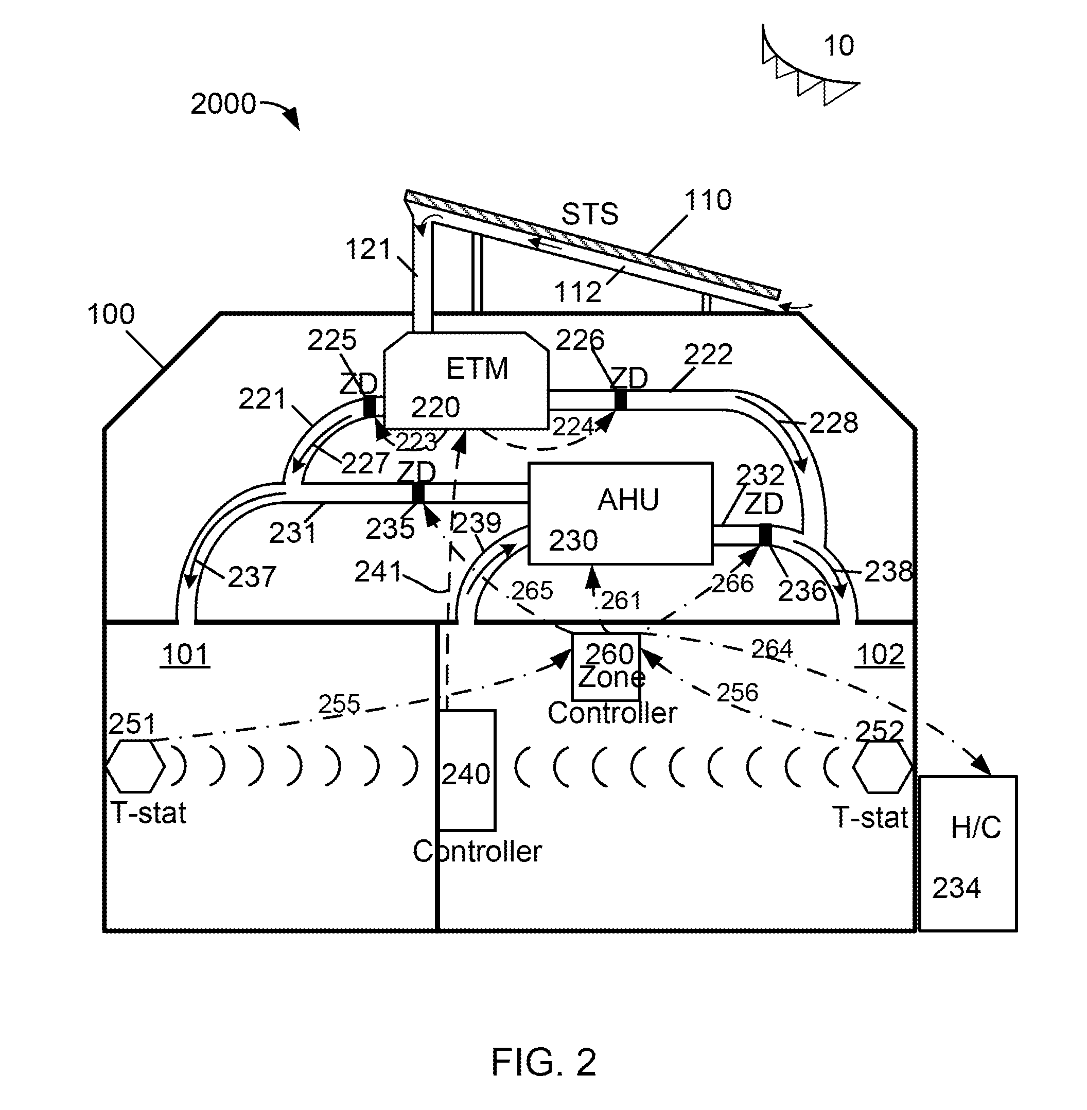
[0026]The present invention relates to operation of a home energy system for building zone control. More particularly, the present invention provides a system and method for providing space conditioning zone control for a building structure with multiple spatial zones within a home energy system utilizing solar thermal energy. Merely, by way of example, the present invention has been applied to transfer solar thermal energy in coordination with an operation of auxiliary thermal module for providing space conditioning for multiple spatial zones of a building structure with efficient energy use and conservation of energy resources, but it would be recognized that the invention has a much broader range of applications.

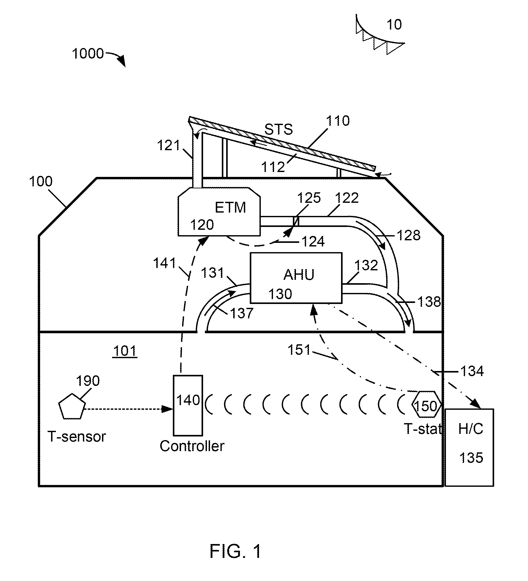
[0027]FIG. 1 is a simplified diagram of a home energy system with space conditioning zone control according to an embodiment of the present invention. This diagram is merely an example, which should not unduly limit the scope of the claims herein. One of ordinary skill in...


PUM


Abstract

A system provides space conditioning zone control in a building for efficient energy use and conservation of energy resources. The system includes an energy transfer module coupled to a solar thermal system to receive a first airflow and an auxiliary thermal module coupled to the energy transfer module for processing a return airflow to provide a conditioned airflow for one or more spatial zones. The system further includes a zone controller coupled directly to the auxiliary thermal module and a thermostat in each spatial zone for operating the auxiliary thermal module. Furthermore, the system includes a master control module wirelessly communicated with each thermostat and configured to operate the energy transfer module. The master control module initiates a transfer of the first airflow based upon a first setpoint before the zone controller initiates a generation and transfer of the conditioned airflow based upon a second setpoint.

Description

CROSS-REFERENCES TO RELATED APPLICATIONS[0001]Not ApplicableSTATEMENT AS TO RIGHTS TO INVENTIONS MADE UNDER FEDERALLY SPONSORED RESEARCH AND DEVELOPMENT[0002]Not ApplicableREFERENCE TO A “SEQUENCE LISTING,” A TABLE, OR A COMPUTER PROGRAM LISTING APPENDIX SUBMITTED ON A COMPACT DISK[0003]Not ApplicableBACKGROUND OF THE INVENTION[0004]The present invention relates to solar energy application for home space conditioning and zoning control. More particularly, the present invention provides a system and method for providing space conditioning zone control for a building structure utilizing solar thermal energy. Merely, by way of example, the present invention has been applied to a home energy system including an energy transfer module controlled by a system controller communicating wirelessly with multiple thermostats coupled to a zone controller for providing space conditioning zone control, but it would be recognized that the invention has a much broader range of applications.[0005]Ove...

Claims


Application Information

Patent Timeline
Patent Type & Authority Applications(United States)
IPC IPC(8): G06F1/32F24J2/00G05D23/19
CPCF24F5/0046F24F11/006F24F2005/0064F24F2011/0068G05D23/1924F24J2/04Y02B10/20Y02B10/24Y02E10/44F24F2011/0075F24F11/30F24F11/62F24F11/56F24F11/46Y02A30/272F24S10/00F24F11/52F24F11/77F24F11/58F24F11/67
Inventor NARAYANAMURTHY, RAMACHANDRANPLAISTED, JOSHUA R.
Owner FTC SOLAR INC
Why Eureka
Try Eureka