Organic Electroluminescent Device

an electroluminescent device and organic technology, applied in static indicating devices, instruments, other domestic objects, etc., can solve the problems of affecting the angular colour variation of the device, the diffraction grating cannot be retracted, and the device's underlying layer may be damaged, so as to reduce the angular colour variation induced by optical structures such as diffraction gratings. , the effect of reducing the angular colour variation

Inactive Publication Date: 2011-10-06
CAMBRIDGE DISPLAY TECH LTD
View PDF6 Cites 25 Cited by
  • Summary
  • Abstract
  • Description
  • Claims
  • Application Information

AI Technical Summary

Benefits of technology

[0011]The present applicant has found that the angular colour variation induced by optical structures such as diffraction gratings can be reduced by combining such optical structures with an overlying microlens array. The microlens array tends to average perceived light over space and wavelength thus reducing angular colour variations. As such, the microlens array and the diffraction grating (or other optical structure which increases angular colour variations) act in a complementary manner.

Problems solved by technology

A problem with organic electroluminescent devices is that much of the light emitted by organic light-emitting material in the organic light-emitting layer does not escape from the device.
The light may be lost within the device by scattering, internal reflection, wave guiding, absorption and the like.
One possible problem with the aforementioned arrangement is that forming an optical structure in the thin film encapsulant by, for example, embossing can damage underlying layers of the device.
Another problem with the aforementioned arrangement is that there is still a significant amount of light lost at the interface between the top electrode of the organic electroluminescent device and the bottom surface of the encapsulant.
However, one problem with such structures is that they tend to increase angular variations in colour.

Method used


Image

  • Organic Electroluminescent Device
  • Organic Electroluminescent Device
  • Organic Electroluminescent Device

Examples


Embodiment Construction

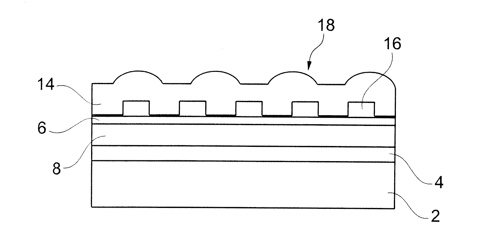
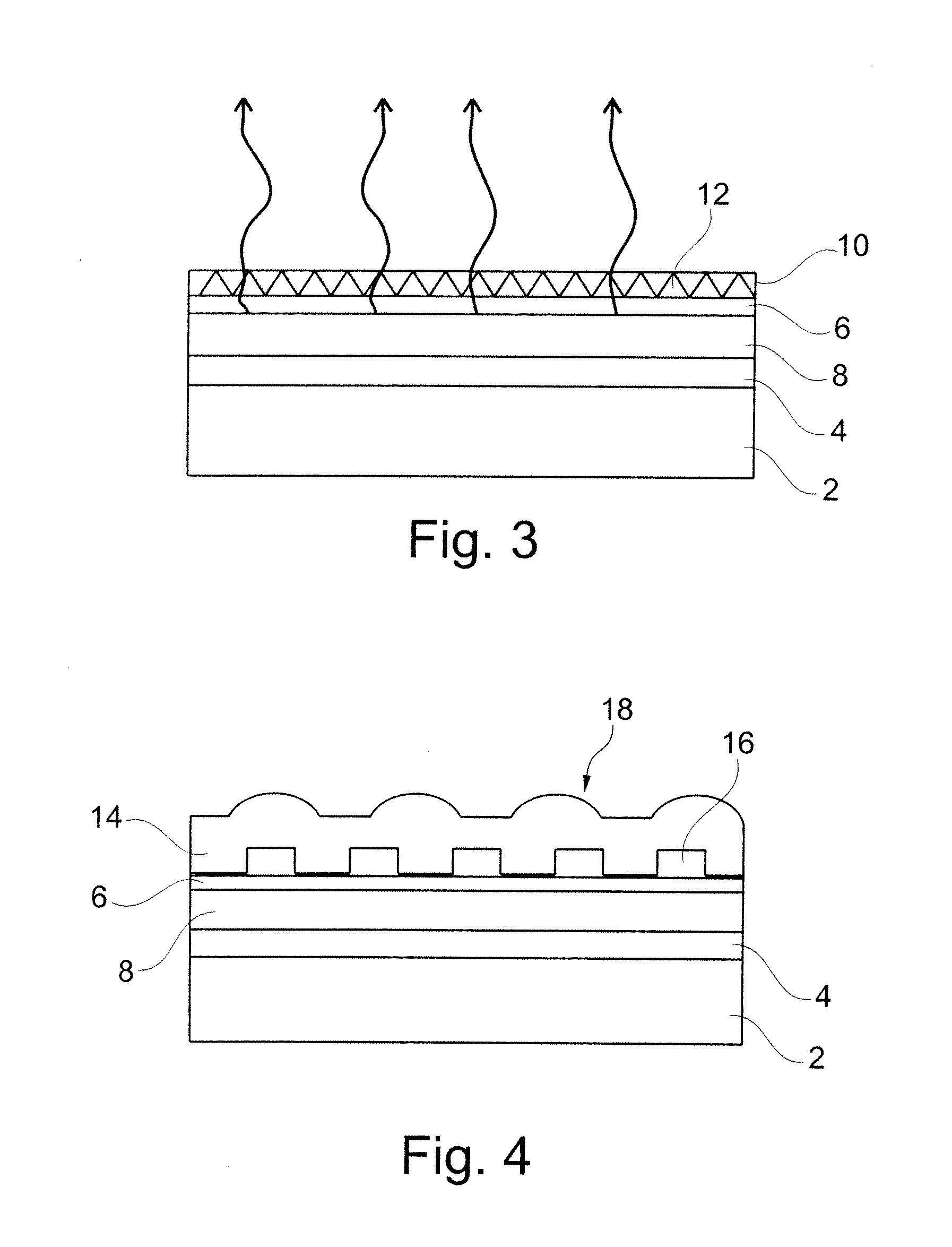
[0033]FIG. 4 shows a top-emitting organic light emitting device in accordance with an embodiment of the present invention. The structure of the device is similar in many respects to the prior art arrangement illustrated in FIG. 3 and like reference numerals have been used for like parts. As in the arrangement of FIG. 3, the device comprises: a substrate 2; a first electrode 4 disposed over the substrate 2 for injecting charge of a first polarity; a second electrode 6 disposed over the first electrode 4 for injecting charge of a second polarity opposite to the first polarity; and an organic light emitting layer 8 disposed between the first and the second electrode. The difference between the arrangement illustrated in FIG. 4 and that illustrated in FIG. 3 lies in the provision of a double side structured encapsulant film 14 rather than a single side structured encapsulant film 10. The double side structured encapsulant film 14 comprises an optical structure 16 (in this case a diffrac...


PUM

PropertyMeasurementUnit
thickaaaaaaaaaa
thickaaaaaaaaaa
widthaaaaaaaaaa

Abstract

An organic electroluminescent device comprising: a substrate; a first electrode disposed over the substrate for injecting charge of a first polarity; a second electrode disposed over the first electrode for injecting charge of a second polarity opposite to said first polarity; an organic light emitting layer disposed between the first and the second electrode, the second electrode being transparent to light emitted by the light emitting layer; and a transparent encapsulant disposed over the second electrode, wherein the transparent encapsulant comprises a microlens array formed by a top surface of the transparent encapsulant and a diffraction grating formed by a bottom surface of the transparent encapsulant.

Description

FIELD OF THE INVENTION[0001]The present invention relates to an organic electroluminescent device and a method of manufacture thereof.BACKGROUND OF THE INVENTION[0002]Organic electroluminescent devices are known, for example, from PCT / WO / 13148 and U.S. Pat. No. 4,539,507. Examples of such devices are shown in FIGS. 1 and 2. Such devices generally comprise: a substrate 2; a first electrode 4 disposed over the substrate 2 for injecting charge of a first polarity; a second electrode 6 disposed over the first electrode 4 for injecting charge of a second polarity opposite to said first polarity; an organic light emitting layer 8 disposed between the first and the second electrodes; and an encapsulant 10 disposed over the second electrode 6. In one arrangement shown in FIG. 1, the substrate 2 and first electrode 4 are transparent to allow light emitted by the organic light-emitting layer 8 to pass therethrough. In another arrangement shown in FIG. 2, the second electrode 6 and the encapsu...

Claims


Application Information

Patent Timeline
Patent Type & Authority Applications(United States)
IPC IPC(8): H01L33/58B29D11/00G02B5/18
CPCH01L51/0035H01L51/0037H01L51/5275H01L51/0039H01L51/5253H01L51/0038H10K85/111H10K85/115H10K85/1135H10K85/114H10K50/858H10K50/844H05B33/22G09G3/3208H10K50/805H10K50/85H10K50/841
Inventor CARTER, JULIANLI, SHUNPU
Owner CAMBRIDGE DISPLAY TECH LTD
Why Eureka
Try Eureka