Stator coil coolant flow reduction monitoring

a stator coil and coolant flow technology, applied in the direction of digital computer details, special data processing applications, automatic disconnection emergency protection arrangements, etc., can solve the problems of coil failure, forced outage of electric generators, and reduced coolant flow

a stator coil and coolant flow technology, applied in the direction of digital computer details, special data processing applications, automatic disconnection emergency protection arrangements, etc., can solve the problems of coil failure, forced outage of electric generators, and reduced coolant flow

US20110241458A1Active Publication Date: 2011-10-06GENERAL ELECTRIC CO

Image

  • Stator coil coolant flow reduction monitoring
  • Stator coil coolant flow reduction monitoring
  • Stator coil coolant flow reduction monitoring

Examples


Embodiment Construction

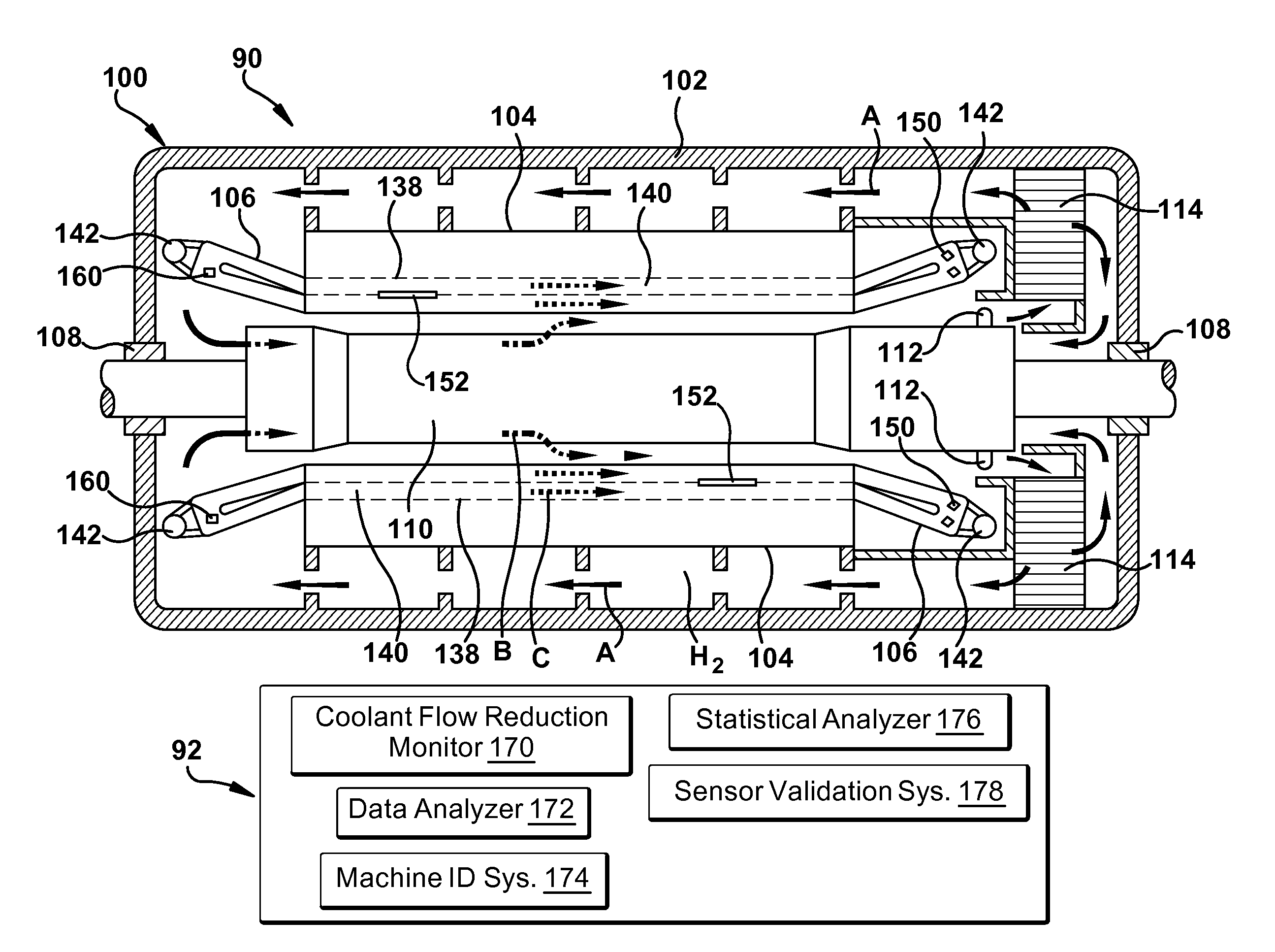
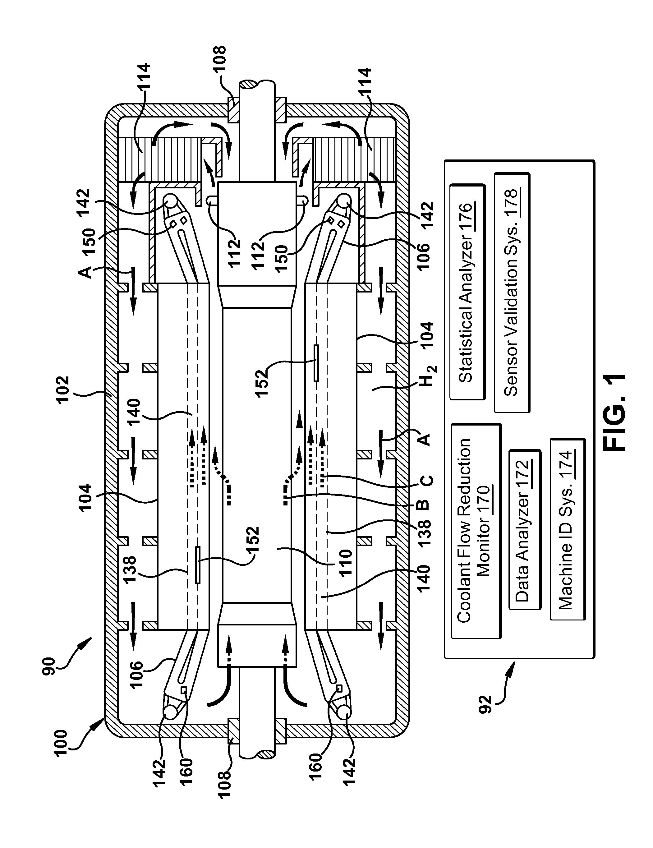
[0012]Referring to FIG. 1, a cross-sectional side view of a rotary electric machine 90 having stator coils cooled by a coolant flowing in a plurality of passages provided in the stator coils is illustrated according to embodiments of the invention. In one example, the rotary electric machine includes a generator 100, as illustrated. However, the teachings of the invention are not so limited. A coolant flow reduction monitoring system 92 for generator 100, as will be described in greater detail herein, is also illustrated in schematic form. Although not shown, monitoring system 92 may include an interface (e.g., a graphical user interface) for a user to input unit specific configurable parameters such as thresholds, machine rating like MegaWatts, machine model, armature current, Mega Volt Ampere (MVA), etc., as will be described herein. As used herein, “flow reduction” may include any type of decreased coolant flow from a maximum flow capability up to and including coolant flow block...


PUM


Abstract

A coolant flow reduction monitoring system for a rotary electric machine having stator coils within a plurality of slots of a stator thereof is provided. The stator coils are cooled by a coolant flowing in a plurality of passages provided in the stator coils. The system includes an outlet temperature sensor for measuring a coolant outlet temperature of the coolant in an outlet of at least one of the plurality of passages, a slot temperature sensor for measuring a temperature in at least one slot at a location along a length of each slot and outside of the stator coils, and an inlet temperature sensor for measuring a coolant inlet temperature of the coolant. A coolant flow reduction monitor generates an alarm indicating a coolant flow reduction based on the at least one coolant outlet temperature, the at least one slot temperature and the coolant inlet temperature.

Description

BACKGROUND OF THE INVENTION[0001]The disclosure relates generally to rotary electric machines, and more particularly, to monitoring of stator coil coolant flow reduction.[0002]Rotary electric machines such as an electrical generator include a rotor within a stator, the latter of which includes a number of conductor sections having slots therein into which stator coils are placed. During operation or, specifically, delivering output power, the generator creates heat such that direct liquid cooling of the stator coils is required to prevent overheating. A cooling liquid, e.g., de-ionized water with anti-freeze, is passed through passages in the stator coils. One challenge relative to the cooling process is that coolant flow is subject to flow reduction up to and including complete blockage, either of which can cause a forced outage of the electric generator. A portion of the stator coils can have a coolant flow reduction due to, for example, debris, loose solids, swelling of existing ...

Claims


Application Information

Patent Timeline
06 Oct 2011
Publication
US20110241458A1
IPC
H02K9/24; H02K11/00; H02H7/08; G06F19/00
CPC
G01K13/02; G01K2013/026; H02K9/08; H02K11/0047; H02K9/24; H02K11/25; G01K13/026
Inventors
RAI, SUDHANSHU; PICCIRILLO, NICOLA