
Device for mounting a resolver in an electric machine

Inactive Publication Date: 2011-10-06
MICHELIN & CO CIE GEN DES ESTAB MICHELIN
View PDF4 Cites 22 Cited by
  • Summary
  • Abstract
  • Description
  • Claims
  • Application Information

AI Technical Summary

Benefits of technology

[0016]Both in its most general aspect and also in the preferred embodiment which has just been defined, the mounting device according to the invention makes it possible to avoid numerous difficulties encountered in the prior art, particularly in the quasi general case where the connections between the resolver stator and the control unit which manages the operation of the machine are effected by flexible conductors. It has indeed been seen that the members for adjusting and fixing the angular position of the stator may indeed interfere with these connections. Moreover, for the requirements of the adjustment proper, it is necessary to leave sufficient “slack” in the strands of these conductors which link the windings of the stator with the exterior of the machine to permit the rotation of the stator in either direction according to the needs of the adjustment. It is thereafter necessary to be able to manage the housing of the excesses of variable length of these strands during the fixing of the stator and then when closing the housing of the assembly in the casing.
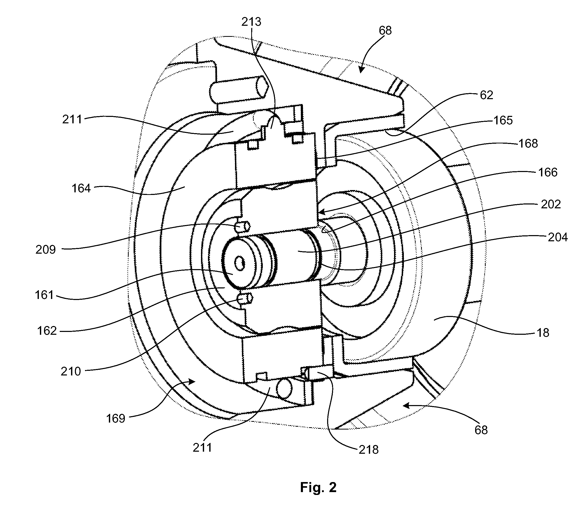
[0022]Thus the invention makes it possible to effect a resolver mounting in which, during assembly, the elements of the rotor and of the stator of the machine are installed in the casing and the rotor shaft mounted in the bearings provided for this purpose. Next, the resolver rotor may be mounted on the shaft of the machine by sliding it axially on the particular fixing device provided by friction from the end of the said shaft in the housing of the resolver up to its operational position. The resolver stator can thereafter be mounted around the rotor in its housing provided for this purpose. The angular setting of the resolver rotor with respect to its stator may be performed from this same end of the shaft, before housing at the end of the casing is reclosed. It is noted that once this adjustment has been performed, if an intervention requires access to the shaft of the machine, necessitating for example the withdrawal of the whole of the machine rotor from its stator, this withdrawal may be done without dismounting the resolver rotor from its position on the shaft and consequently without needing to redo the adjustment of the resolver for this reason alone on remounting the shaft.

Problems solved by technology

It has indeed been seen that the members for adjusting and fixing the angular position of the stator may indeed interfere with these connections.

Method used


Image

  • Device for mounting a resolver in an electric machine
  • Device for mounting a resolver in an electric machine
  • Device for mounting a resolver in an electric machine

Examples


Embodiment Construction

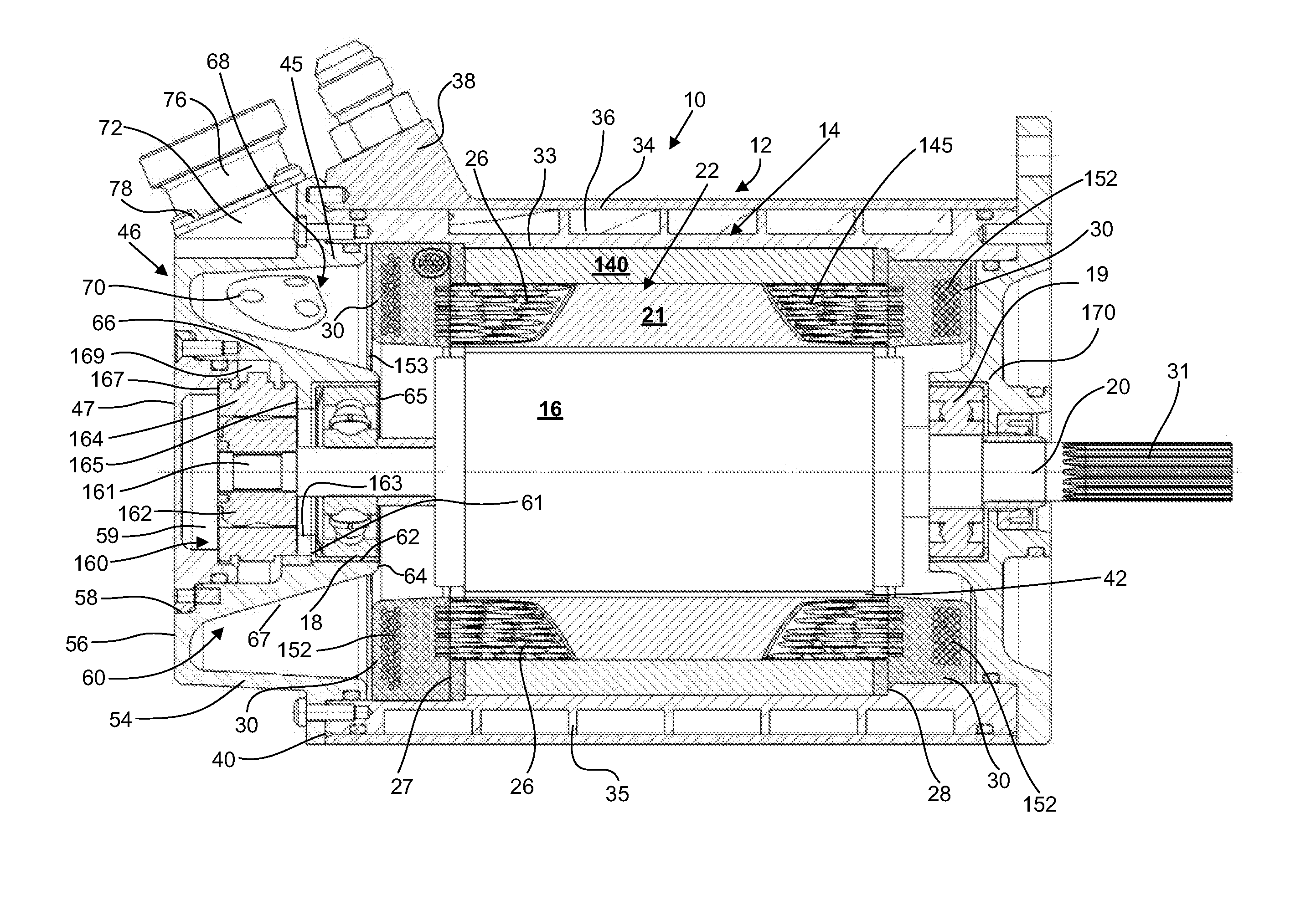
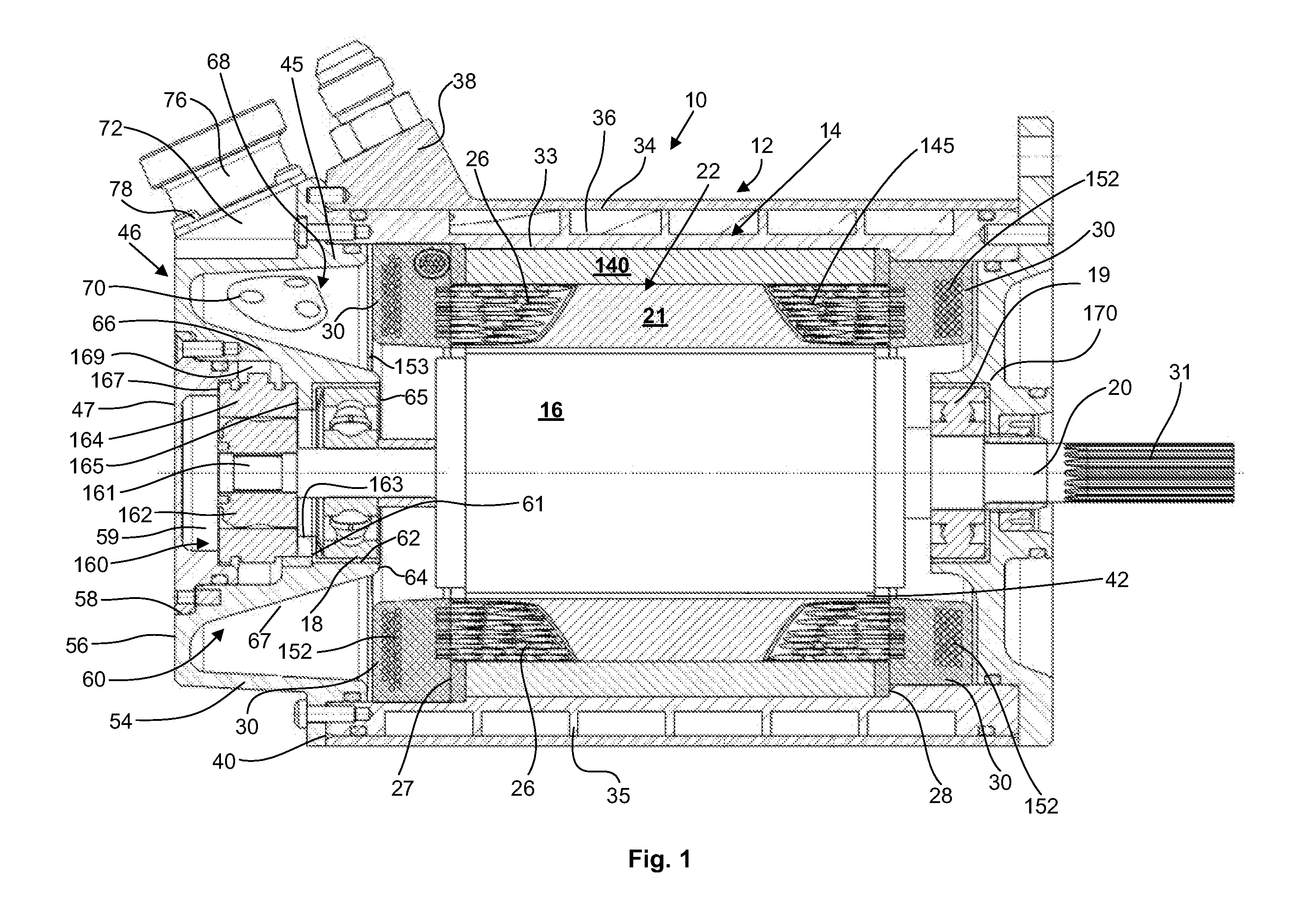
[0029]A synchronous electric machine 10 represented in FIG. 1 comprises an external casing 12 inside which are housed a stator 14 and a rotor 16 mounted for rotation with respect to the stator around an axis 20 inside the stator. The rotor is mounted on a shaft 31 engaged in roller bearings 18 and 19 secured to the casing 12. The stator 14 comprises a magnetic circuit 22 which comprises a first generally cylindrical stack 21 of magnetic laminations. The stack 21 is hollowed out with a series of peripheral notches 26 which, without being parallel to the axis 20, run between one of its axial end faces 27 and its other axial end face 28, while remaining circumscribed inside a virtual cylindrical ring.

[0030]A yoke 140 consisting of a cylindrical stack of laminations in the form of circular rings surrounds the stack 21 and closes the radially external ends of the notches 26, so ensuring the continuity of the magnetic circuit 22. In the notches 26 are housed, in a well-known manner, coppe...


PUM


Abstract

An electric machine with a resolver for a system for autocontrol of the machine includes a machine stator, a machine rotor mounted for rotation in the stator, the rotor being mounted on a shaft, and a casing enclosing this assembly. The resolver includes a fixed resolver stator centred axially in a housing inside the casing and a resolver rotor mounted on the shaft of the machine rotor inside the resolver stator. The resolver stator is locked in an axially and angularly fixed position in the housing. A mounting device is included for mounting the resolver. The mounting device includes a bearing for rotational adjustment of an angular position of the resolver rotor on the shaft of the machine rotor and a device for clamping the resolver rotor and the shaft with respect to one another in a chosen angular position. The device may include a friction race.

Description

FIELD OF THE INVENTION[0001]The present invention relates to rotating electric machines. It is aimed especially at machines capable of deploying significant powers in a very compact format, especially when they operate as a motor, for example for traction applications aboard automotive vehicles.RELATED ART[0002]Proposals for electric vehicles have multiplied in recent years. Electric motors have begun to appear whose power can reach for example 20 or indeed 30 kW within confines compatible with the interior of a vehicle wheel or its immediate environment in the case of a vehicle comprising an electric machine for each wheel. Having regard to the significant electrical power deployed by these machines in a restricted space, the arrangement of the functional members such as the stator, the rotor and the accessory elements necessary for controlling the machine inside the casing remains an essential concern for the designers of machines of this type.[0003]According to a mode of construc...

Claims


Application Information

Patent Timeline
IPC IPC(8): H02K11/00
CPCH02K1/28H02K5/06H02K15/16H02K5/225H02K11/0031H02K5/1732H02K11/225
Inventor VEDY, BERTRAND
Owner MICHELIN & CO CIE GEN DES ESTAB MICHELIN
Learn More